Blogger Themes

Tuesday 29 November 2011

The Next Generation of Nuclear Reactors

Engineerblogger
Nov 29, 2011


The nuclear-power-generation future is quietly taking shape, at least virtually, through the labors of several hundred scientists and technicians working on the Next Generation Nuclear Plant (NGNP) at the Idaho National Laboratory (INL) in Idaho Falls, ID. Scattered through several research facilities and operating sites, these experts are wrestling with dozens of questions—from technology evaluations to site licensing to spent fuels—that accompany any extension of nuclear power.


High-temperature gas-cooled reactor.
Image courtesy of Idaho National Laboratory (INL).


NGNP is far more than an extension: it is a radical step forward for nuclear power. It will be the first truly new reactor design to go into commercial service in the U.S. in decades; it is to be up and running by September 2021. The way forward may not be smooth. Cost estimates range from $4 billion to nearly $7 billion and who pays for what remains unsettled. Nevertheless, barring a technical crunch, a licensing snag, or a financial meltdown, NGNP could become a cornerstone of an energy future with abundant electricity and drastically reduced carbon emissions.

The reactor initiative is for a high-temperature gas-cooled reactor or HTGC (sometimes abbreviated as HTGR), a graphite-moderated and helium-cooled design backed by considerable engineering development in Japan, China, Russia, South Africa, and, in the U.S. by General Atomics, Inc. The primary goal of the project is to commercialize HTGCs. Experts put the potential market at several hundred reactors if most coal-fired power plants are replaced.


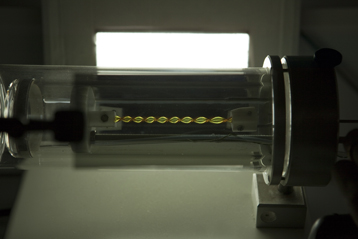
Researcher at Idaho National Laboratory (INL).


Running NGNP is what the U.S. Department of Energy calls the NGNP Industry Alliance. Members include many of power-generation’s biggest names: General Atomics; Areva NP; Babcock & Wilcox; Westinghouse Electric Co.; SGL Group, a German producer of graphite and carbon products; and Entergy Nuclear. Entergy owns, operates, or manages 12 of the 104 power-gen reactors in the U.S. and is expected to handle licensing. These firms’ operations and expertise span the industry.

Further backing comes from the consortium that operates INL itself. Its members are Battelle Energy Alliance / Battelle Memorial Institute; Babcock & Wilcox; Washington Group International / URS Corp.; Massachusetts Institute of Technology; and the Electric Power Research Institute.

The high-temperature reference is to the reactor’s outlet temperature, about 1,000 °C, or very roughly three times higher than most of today’s reactors. That means HTGCs can be a source of low-carbon, high-temperature process heat for petroleum refining, biofuels production, the production of fertilizer and chemical feedstocks, and reprocessing coal into other fuels, among other uses. This is why the NGNP alliance includes Dow Chemical, Eastman Chemical, ConocoPhillips, Potash Corp., and the Petroleum Technology Alliance of Canada. All are potential customers for NGNP’s clean heat.

The NGNP Industry Alliance’s HTGC is an integral part of the Generation IV International Forum (GIF). Founded in 2000, GIF is a broadly based international effort to put nuclear power to widespread use for base-load electricity generation and low-cost heat for industrial processes. The other five Generation IV designs are molten-salt reactors, sodium-cooled fast, supercritical water-cooled, gas-cooled fast, and lead-cooled fast. (“Fast” refers to a portion of the neutron spectrum.)

Improvements to existing reactors of 2000 and later are classed as Generation III reactors. They have:
  • standardized type designs to expedite licensing, reduce capital costs, and speed construction. Gen II’s were largely custom-built.
  • simpler, more rugged designs for less complicated operation and lower vulnerability to operational problems.
  • higher availability with fewer, shorter outages and operating lives stretching 60 years.
  • better resistance to damage from possible core melts and aircraft impact.
  • "grace periods" of 72 hours; a shutdown plant requires no active intervention for the first 72 hours in part because of passive or inherent safety features that rely on gravity, natural convection, or resistance to high temperatures.
  • higher "burn up" to reduce fuel use and the amount of waste.

There is also a Gen III-plus group of about a dozen reactor designs in advanced planning stages. Today’s operating units, mostly built since 1970, are second generation. The first generation was 1950 - 1970 prototypes and demonstration units.

Despite optimistic long-term prospects for NGNP and Gen-IV, the nuclear industry’s critics raise two objections. First, safety risks may be greater initially with new reactor types as reactor operators will have had little experience with the new design. Second, fabrication, construction, and maintenance of new reactors can be expected to have a steep learning curve. Advanced technologies always carry a higher risk of accidents and mistakes than predecessors. Established technologies grow safer with accumulated experience and lessons-learned.

The NGNP program envisions dozens of these reactors by 2050. In contrast to today’s power-generation reactors and their enormous concrete-and-steel containment structures, these reactors may be nearly invisible. They will be underground in concrete silos 150 feet deep.

Meanwhile, ASME is playing a major role in NGNP research on metal alloys that can withstand the reactors’ extremely high outlet temperatures. The alloys under consideration are 800H (iron-nickel-chromium), Grade 91 steel (chromium–molybdenum) and Haynes International’s Hastelloy XR (nickel-chromium-iron-molybdenum). The work is being carried out by ASME Standards Technology LLC under an agreement with the U.S. Department of Energy.

Source: ASME

TIME Magazine recognizes DARPA’s Hummingbird Nano Air Vehicle

Engineerblogger
Nov 29, 2011


Rapidly flapping wings to hover, dive, climb, or dart through an open doorway, DARPA’s remotely controlled Nano Air Vehicle relays real-time video from a tiny on-board camera back to its operator. Weighing less than a AA battery and resembling a live hummingbird, the vehicle could give war fighters an unobtrusive view of threats inside or outside a building from a safe distance. This week, TIME Magazine named the Hummingbird one of the best 50 inventions of the year, featuring it on the November 28th cover.

“The Hummingbird’s development is in keeping with a long DARPA tradition of innovation and technical advances for national defense that support the agency’s singular mission – to prevent and create strategic surprise,” said Jay Schnitzer, DARPA’s Defense Sciences Office director.

Creating a robotic hummingbird, complete with intricate wings and video capability, may not have seemed doable or even imaginable to some. But it was this same DARPA visionary innovation that decades ago led to unmanned aerial vehicles (UAVs), which were, at the time, inconceivable to some because there was no pilot on board. In the past two years, the Air Force has trained more initial qualification pilots to fly UAVs than fighters and bombers combined.

“Advances at DARPA challenge existing perspectives as they progress from seemingly impossible through improbable to inevitable,” said Dr. Regina Dugan, DARPA’s director.

UAVs from the small WASP, to the Predator, to Global Hawk now number in the hundreds in Afghanistan. What once seemed inconceivable is now routine.

“At DARPA today we have many examples of people – national treasures themselves – who left lucrative careers, and PhD programs, to join the fight,” Dugan said. “Technically astute, inspiringly articulate, full of ‘fire in the belly,’ they are hell-bent and unrelenting in their efforts to show the world what’s possible. And they do it in service to our Nation.”

TIME Magazine also recognized DARPA’s innovative breakthrough in 3-D holography, the Urban Photonic Sandtable Display, among its top 50 inventions. The holographic sand table could give war fighters a virtual mission planning tool by enabling color 3-D scene depictions, viewable by 20 people from any direction—with no 3-D glasses required.


Source: DARPA

Ride the wave: vessels for wind turbine maintenance

The Engineer
Nov 28, 2011

Softening the blow: the craft’s pods adapt to the water’s undulating surface, minimising bumps

A sea craft using supercar suspension could be the solution to maintaining offshore wind turbines.

It’s probably fair to say that wind turbines have become one of the most divisive forms of renewable energy available in the UK.

But whichever side of the fence you sit on, from a purely technical point of view it’s difficult to deny that the wind sector presents some unique and interesting engineering challenges.

For onshore turbines, engineers have risen to this quite impressively, demonstrating an ability to effectively transfer knowledge and skills from other sectors to solve issues such as torque handling with innovative gearless generators, for example.

With offshore, though, there is a whole new set of challenges to tackle and not just from a scale point of view.

Even the most robust turbines will be subject to routine maintenance and unscheduled downtime. So if the planned next-generation offshore mega-farms are going to be cost effective, engineers will need to get to them in potentially rough sea conditions or the turbines will sit idle and lose money (see panel).

For this reason, the UK Carbon Trust - through its industry-backed Wind Accelerator Programme - launched a competition this summer in order to find technologies that might help achieve this. The potential solutions detailed in the entries submitted so far are varied, but one thing they have in common is the need for some kind of vessel that can cope with large waves.

Continuing the tradition in the renewable sector of transferring technologies from other sectors, one of the potential solutions has its roots in the automotive industry.

Nauti-Craft is an Australian company headed by inventor and engineer Chris Heyring. While Nauti-Craft is focused on marine applications, it draws experience and ideas from a previous company co-founded by Heyring called Kinetic, which builds innovative suspension systems for high-performance cars.

These were used by Citroen to win the World Rally Championship in 2003, 2004 and 2005 and by Mitsubishi to win the Paris Dakar campaign in 2004 and 2005 - until, as Heyring puts it, ’they were banned for being too competitive’. The suspension systems are now fitted as standard to the current Toyota Landcrusier and Nissan Patrol off-roaders, as well as the McLaren MP4-12C supercar.

Monday 28 November 2011

Everyday Prothetic Finger

Engineerblogger
Nov 28, 2011


X-Fingers surgical steel fingers.


In a former life, Dan Didrick fabricated cosmetic fingers. The key word in that phrase is cosmetic.

“The fingers were only a silicon cap that doesn’t bend,” Didrick said. “We call them Sunday fingers because you wear them to church or dinner and then throw them in a drawer for the week.”

Bedeviled by the cosmetic fingers’ shortcomings, he invented X-Finger, surgical steel fingers that move, flex, and grasp, just like the wearer’s original fingers.

“You can move them as quickly as you can move your prior finger; plus because it’s common to flex your finger from open to closed and the X Finger follows motion of a residual finger, there’s no learning curve,” Didrick said. “A patient can use the device right away after putting it on. They could immediately catch a tossed ball that they see from the corner of their eye.”


Along the 10-year path since his first prototype, Didrick patented the device—which uses no electronics—himself, sought and received coverage from all major medical insurers for the fingers, and taught himself computer-aided design (CAD). That last bit, he said, was the easiest.

A huge proportion of nonfatal accidental amputations involve fingers. The U.S. Bureau of Labor Statistics estimates that finger losses account for about 94 % of job-related amputations.

So Didrick—who got his start in prosthethics as a child, by using materials from his father’s dental office to make movie-quality monster masks—put his skills to use fabricating prosthetic fingers.


But his world, and his job, changed when he met a man who had lost several fingers in an accident and who was deaf. The loss of the fingers made it impossible to communicate in sign language.

“I started by actually carving components out of wood and assembling them into reciprocating series of components that, through leverages, force the mechanics in the shape of a finger to move from a straight to a bent position; from straight to a fist,” Didrick said.

Many amputees retain part of their finger. So the device, when fitted over the hand and the residual finger or fingers, lets a patient move his or her X-Finger by moving the residual finger from extended to bent.


X-Fingers, invented by Dan Didrick, are prosthetic fingers that can be manipulated by wearers through use of their residual finger or fingers. The device lets them regain full use of their finger or fingers.

“So I came up with the assembly, but I was just carving them out of wood,” Didrick said. “Then I started seeking out design engineers. That’s when I realized it can cost tens of thousands of dollars to have a design engineer create an assembly of this nature.”

Though he had majored in business in college, Didrick rose to this first challenge as he would rise to many others while launching X-Finger. He simply bought a CAD package—SolidWorks, from the company in Concord, MA—and quickly ran through the tutorial.

“Then I just started designing the components,” he said. “It only took about two weeks to get the first design. I shipped those to a manufacturer and they replicated them using an EDM machine and sent back components.”

Because all amputation cases are different, Didrick went on to develop what he called an erector set of parts that could be assembled into more than 500 different configurations. That number is likely much higher than 500, but “once I got that high, I became confused counting them,” he said.

The device is composed of stainless steel, with a plastic cap that sits on the tip of the finger and another bit of plastic that sits at the flange. This is covered with a thermoplastic cosmetic skin that is soft and resists tearing. Think of what an artificial fishing worm feels like and how it can stretch.

“We actually contacted a company that was doing a job for the military, and they’d formulated thermoplastic to the same durometer reading as human skin; so it’s almost eerie to touch it, in that it feels like skin,” Didrick said.

Each finger contains 23 moving parts, though depending on the complexity of the case—such as whether the wearer retains a residual finger or not—it could contain more. For those without residual fingers, a wire runs into the webbing between the fingers to receive open and flex impulses. The device is attached to the wrist and fitted over the hand and the residual fingers.

“It was really challenging replacing the ring and middle finger. The joint that controls those residual fingers is in your hand,” Didrick said. “But in this case it needs a probe that goes down into the webbing between the fingers to be controlled by that joint.

For those who have lost four fingers, the device allows the movement of the palm to control all the artificial fingers.

Post Engineering

Though he’d invented the world’s first active prosthetic finger (the passive type is the cosmetic ‘Sunday’ finger), Didrick, who now owns Didrick Medical of Naples, FL, was still an industry outsider.

He bought a book called Patent It Yourself by David Pressman (1979 McGraw-Hill and since updated) and spent a year writing his own patent.

Once the device was patented, FDA representatives and some online help taught him how to write a 513(d) document necessary for device evaluation. Didrick sent his evaluation to the agency and soon received a positive response. X-Fingers (the plural, used when the device contains more than one finger) had been registered with the FDA.

The next step was receiving insurance approval for the fingers. After he won approval from the FDA, he went on to get approval from all major insurance companies, which now cover X-Fingers.

“From there, the device began taking off. The need was great,” Didrick said. “Many amputees had been awaiting something like this.”

What’s little realized, he said, is how many children lose fingers. The largest group of people who lose fingers outside the workplace are children under five, who undergo finger amputation due to accidents like slamming them in a car door.

He also has learned that one out of 200 people will lose one or more fingers within their lifetime. That statistic takes into account people living all over the world.

“It’s not only machinists who lose fingers,” Didrick said.

Because his device is powered by the body, literally the wearer is flexing and bending his hand.

Many of Didrick’s customers pay a deposit in advance, which helps finance the four-employee company and it’s continued innovations.

What’s New and Next?

After his initial success, Didrick began routinely traveling to the Brooke Army Medical Center in San Antonio and to the Walter Reed Army Medical Center in Washington, DC, to fit wounded soldiers. He has also has fitted British soldiers with the device.

The U.S. Department of Defense asked him to design an artificial thumb, which he has also done. It’s not surprisingly called the X-Thumb.

He’s now at work on a thin glove that would enable those with paralyzed hands who retain some mobility in the wrist to use that mobility to control their hands.

Didrick is also trying to help children whose insurance companies deny them coverage because they grow out of their prosthetics too fast. The costs of producing children’s X-Fingers are high because of the variation in injuries and finger dimensions in smaller fingers and hands. He’s recently established the nonprofit 501(c)(3) organization, World Hand Foundation, to cover costs to provide X-Fingers for those who cannot afford to pay for them.

And he’s still using his original CAD package.

“If we needed the funds to hire a professional design team we’d never be able to do this,” Didrick said.

Source: ASME

Robots in reality: Robots for real-world challenges

MIT News
Nov 28, 2011

Nicholas Roy, an MIT associate professor of aeronautics and astronautics
Photo: Dominick Reuter

Consider the following scenario: A scout surveys a high-rise building that’s been crippled by an earthquake, trapping workers inside. After looking for a point of entry, the scout carefully navigates through a small opening. An officer radios in, “Go look down that corridor and tell me what you see.” The scout steers through smoke and rubble, avoiding obstacles and finding two trapped people, reporting their location via live video. A SWAT team is then sent to lead the workers safely out of the building.

Despite its heroics, though, the scout is impervious to thanks. It just sets its sights on the next mission, like any robot would do.

In the not-too-distant future, such robotics-driven missions will be a routine part of disaster response, predicts Nicholas Roy, an MIT associate professor of aeronautics and astronautics. From Roy’s perspective, robots are ideal for dangerous and covert tasks, such as navigating nuclear disasters or spying on enemy camps. They can be small and resilient — but more importantly, they can save valuable manpower.

The key hurdle to such a scenario is robotic intelligence: Flying through unfamiliar territory while avoiding obstacles is an incredibly complex computational task. Understanding verbal commands in natural language is even trickier.

Both challenges are major objectives in Roy’s research — and with both, he aims to design machine-learning systems that can navigate the noise and uncertainty of the real world. He and a team of students in the Robust Robotics Group, in MIT’s Computer Science and Artificial Intelligence Laboratory (CSAIL), are designing robotic systems that “do more things intelligently by themselves,” as he puts it.

For instance, the team is building micro-aerial vehicles (MAVs), about the size of a small briefcase, that navigate independently, without the help of a global positioning system (GPS). Most drones depend on GPS to get around, which limits the areas they can cover. In contrast, Roy and his students are outfitting quadrotors — MAVs propelled by four mini-chopper blades — with sensors and sensor processing, to orient themselves without relying on GPS data.

“You can’t fly indoors or quickly between buildings, or under forest canopies stealthily if you rely on GPS,” Roy says. “But if you put sensors onboard, like laser range finders and cameras, then the vehicle can sense the environment, it can avoid obstacles, it can track its own position relative to landmarks it can see, and it can just do more stuff.”
To read more click here...

Toyota unveils high-tech concept car ahead of show

Engineerblogger
Nov 28, 2011

A presenter explains about Toyota Fun-Vii in Tokyo Monday, Nov. 28, 2011. Toyota Motor Corp. unveiled the futuristic concept car resembling a giant smartphone to demonstrate how Japan's top automaker is trying to take the lead in technology at the upcoming Tokyo auto show, which opens to the public this weekend. (AP Photo/Koji Sasahara)


Toyota's president unveiled a futuristic concept car resembling a giant smartphone to demonstrate how Japan's top automaker is trying to take the lead in technology at the upcoming Tokyo auto show.

Toyota Motor Corp. will also be showing an electric vehicle, set for launch next year, and a tiny version of the hit Prius gas-electric hybrid at the Tokyo Motor Show, which opens to the public this weekend.

But the automaker's president, Akio Toyoda, chose to focus on the experimental Fun-Vii, which he called "a smartphone on four wheels" at Monday's preview of what Toyota is displaying at the show.

The car works like a personal computer and allows drivers to connect with dealers and others with a tap of a touch-panel door.

"A car must appeal to our emotions," Toyoda said, using the Japanese term "waku waku doki doki," referring to a heart aflutter with anticipation.

Toyota's booth will be a major attraction at the biannual Tokyo exhibition for the auto industry. Toyota said the Fun Vii was an example of what might be in the works in "20XX," giving no dates.

The Tokyo show has been scaled back in recent years as U.S. and European automakers increasingly look to China and other places where growth potential is greater. U.S. automaker Ford Motor Co. isn't even taking part in the show.

Toyota's electric vehicle FT-EV III, still a concept or test model, doesn't have a price yet, but is designed for short trips such as grocery shopping and work commutes, running 105 kilometers (65 miles) on one full charge.

The new small hybrid will be named Aqua in Japan, where it goes on sale next month. Overseas dates are undecided. Outside Japan it will be sold as a Prius.

Japan's automakers, already battered by years of sales stagnation at home, took another hit from the March 11 earthquake and tsunami, which damaged part suppliers in northeastern Japan, and forced the car makers to cut back production.

The forecast of demand for new passenger cars in Japan this year has been cut to 3.58 million vehicles from an earlier 3.78 million by the Japan Automobile Manufacturers Association.

Toru Hatano, auto analyst for IHS Automotive in Tokyo, believes fuel efficient hybrid models will be popular with Japanese consumers, and Toyota has an edge.

"The biggest obstacle has to do with costs, and you need to boost vehicle numbers if you hope to bring down costs" he said. "Toyota has more hybrids on the market than do rivals, and that gives Toyota an advantage."

Toyota has sold more than 3.4 million hybrids worldwide so far. Honda Motor Co., which has also been aggressive with hybrid technology, has sold 770,000 hybrids worldwide.

Toyota is also premiering a fuel-cell concept vehicle, FCV-R, at the show.

Zero-emission fuel cell vehicles, which run on hydrogen, have been viewed as impractical because of costs. Toyota said the FCV-R is a "practical" fuel-cell, planned for 2015, but didn't give its price.

"I felt as though my heart was going to break," Toyoda said of the turmoil after the March disaster. "It is precisely because we are in such times we must move forward with our dreams."

Source: The Associated Press

Mazda announces world first capacitor-based regenerative braking system

Engineerblogger
Nov 28, 2011


Mazda's 'i-ELOOP' regenerative braking system

Mazda Motor Corporation has developed the world's first passenger vehicle regenerative braking system that uses a capacitor. The groundbreaking system, which Mazda calls 'i-ELOOP', will begin to appear in Mazda's vehicles in 2012. In real-world driving conditions with frequent acceleration and braking, 'i-ELOOP' improves fuel economy by approximately 10 percent.

Mazda's regenerative braking system is unique because it uses a capacitor, which is an electrical component that temporarily stores large volumes of electricity. Compared to batteries, capacitors can be charged and discharged rapidly and are resistant to deterioration through prolonged use. 'i-ELOOP' efficiently converts the vehicle's kinetic energy into electricity as it decelerates, and uses the electricity to power the climate control, audio system and numerous other electrical components.

Regenerative braking systems are growing in popularity as a fuel saving technology. They use an electric motor or alternator to generate electricity as the vehicle decelerates, thereby recovering a portion of the vehicle's kinetic energy. Regenerative braking systems in hybrid vehicles generally use a large electric motor and dedicated battery.

Mazda examined automobile accelerating and decelerating mechanisms, and developed a highly efficient regenerative braking system that rapidly recovers a large amount of electricity every time the vehicle decelerates. Unlike hybrids, Mazda's system also avoids the need for a dedicated electric motor and battery.

'i-ELOOP' features a new 12-25V variable voltage alternator, a low-resistance electric double layer capacitor and a DC/DC converter. 'i-ELOOP' starts to recover kinetic energy the moment the driver lifts off the accelerator pedal and the vehicle begins to decelerate. The variable voltage alternator generates electricity at up to 25V for maximum efficiency before sending it to the Electric Double Layer Capacitor (EDLC) for storage. The capacitor, which has been specially developed for use in a vehicle, can be fully charged in seconds. The DC/DC converter steps down the electricity from 25V to 12V before it is distributed directly to the vehicle's electrical components. The system also charges the vehicle battery as necessary. 'i-ELOOP' operates whenever the vehicle decelerates, reducing the need for the engine to burn extra fuel to generate electricity. As a result, in "stop-and-go" driving conditions, fuel economy improves by approximately 10 percent.

The name 'i-ELOOP' is an adaptation of "Intelligent Energy Loop" and represents Mazda's intention to efficiently cycle energy in an intelligent way.

'i-ELOOP' also works in conjunction with Mazda's unique 'i-stop' idling stop technology to extend the period that the engine can be shut off.

Mazda is working to maximize the efficiency of internal combustion engine vehicles with its groundbreaking SKYACTIV TECHNOLOGY. By combining this with i-stop, i-ELOOP and other electric devices that enhance fuel economy by eliminating unnecessary fuel consumption, Mazda is striving to deliver vehicles with excellent environmental performance as well as a Zoom-Zoom ride to all its customers.


Source: Mazda  

Graphene: the future in a pencil trace

Engineerblogger
Nov 28, 2011


The European programme for research into graphene, for which the Universities of Cambridge, Manchester and Lancaster are leading the technology roadmap, today unveiled an exhibition and new videos communicating the potential for the material that could revolutionise the electronics industries.


An exhibition has been launched in Warsaw today highlighting the development and future of graphene, the ‘wonder substance’ set to change the face of electronics manufacturing, as part of the Graphene Flagship Pilot (GFP), aimed at developing the proposal for a 1 billion European programme conducting research and development on graphene, for which the Universities of Cambridge, Manchester and Lancaster are leading the technology roadmap.

The exhibition covers the development of the material, the present research and the vast potential for future applications. The GFP also released two videos aimed at introducing this extraordinary material to a wider audience, ranging from stakeholders and politicians to the general public. The videos also convey the mission and vision of the graphene initiative.

“Our mission is to take graphene and related layered materials from a state of raw potential to a point where they can revolutionise multiple industries – from flexible, wearable and transparent electronics to high performance computing and spintronics” says Professor Andrea Ferrari, Head of the Nanomaterials and Spectroscopy Group.

“This material will bring a new dimension to future technology – a faster, thinner, stronger, flexible, and broadband revolution. Our program will put Europe firmly at the heart of the process, with a manifold return on the investment of 1 billion Euros, both in terms of technological innovation and economic exploitation.”

Graphene, a single layer of carbon atoms, could prove to be the most versatile substance available to mankind. Stronger than diamond, yet lightweight and flexible, graphene enables electrons to flow much faster than silicon. It is also a transparent conductor, combining electrical and optical functionalities in an exceptional way.

Graphene has the potential to trigger a smart and sustainable carbon revolution, impact in information and communication technology is anticipated to be enormous, transforming everyday life for millions.

It is hoped that the unique properties of graphene will spawn innovation on an unprecedented scale for myriad areas of manufacturing and electronics – high speed, transparent and flexible consumer goods; novel information processing devices; biosensors; supercapacitors as alternatives to batteries; mechanical components; lightweight composites for cars and planes.

The Warsaw meeting has seen the gathering of EU and national politicians, national funding bodies and research policy makers, EC representatives, and key stakeholders from the scientific community associated to the pilots. At the meeting, the six short-listed pilots presented their vision, objectives, and expected impact on science, technology and society. This follows a successful meeting in Madrid with over 80 European companies interested in developing graphene science into technology.

Dr Jani Kivioja, from the Cambridge-Nokia Research Centre, said: “We got overwhelming interest in graphene technology from a large number of companies. We are now working to form a Graphene Alliance to formulate and sharpen the graphene technology roadmap for Europe. This alliance of the leading EU technology companies will be instrumental in keeping Europe at the forefront of the graphene technology development. The potential prospects for job and wealth creation are huge.”

Source: Cambridge University

Thursday 24 November 2011

Researchers Draft Blueprint to Boost Energy Innovation

Engineerblogger
Nov 24, 2011


The U.S. government could save the economy hundreds of billions of dollars per year by 2050 by spending a few billion dollars more a year to spur innovations in energy technology, according to a new report by researchers at the Harvard Kennedy School.

Achieving major cuts in carbon emissions in the process will also require policies that put a substantial price on carbon or set clean energy standards, the researchers find.

The report is the result of a three-year project to develop a set of actionable recommendations to achieve “a revolution in energy technology innovation.”

The project, part of the Energy Technology Innovation Policy (ETIP) research group in the Kennedy School’s Belfer Center for Science and International Affairs, included the first survey ever conducted of the full spectrum of U.S. businesses involved in energy innovation, identifying the key drivers of private-sector investments in energy innovation.

The researchers also surveyed more than 100 experts working with an array of energy technologies to get their recommendations for energy R&D funding and their projections of cost and performance under different R&D scenarios. They then used the experts’ input to conduct extensive economic modeling on the impact of federal R&D investments and other policies (such as a clean energy standard) on economic, environmental, and security goals.

The research team identified industries that would most benefit from increased innovation investment. The report recommends the largest percentage increases for research and development in four fields: energy storage, bio-energy, efficient buildings, and solar photovoltaics.

The report, titled Transforming U.S. Energy Innovation, recommends doubling government funding for energy research, development and demonstration efforts to about $10 billion per year. The modeling results suggest that spending above that level might deliver decreasing marginal returns.

The modeling done for the report projected that investing more money in energy innovation without also setting a substantial carbon price or stringent clean energy standards would not bring big reductions in greenhouse gas emissions -- largely because without such policies, companies would not have enough incentive to deploy new energy technologies in place of carbon-emitting fossil fuels.

The researchers also propose ways for the government to strengthen its energy innovation institutions, particularly the national laboratories, so that the United States can get the most bang for its buck in its investments in energy innovation. The report concludes that the national laboratories suffer from fast-shifting funding and lack incentives for entrepreneurship.

The researchers also find that the performance of public-private partnerships and international partnerships on energy innovation would benefit from gathering information about the performance of previous projects.

The ETIP project is part of the Science, Technology, and Public Policy Program and Environment and Natural Resources Program at the Kennedy School. Professor Venkatesh Narayanamurti and Associate Professor Matthew Bunn were the principal investigators for this work, and the research team was led by Dr. Laura Diaz Anadon, ETIP director. The project was supported by a generous grant from the Doris Duke Charitable Foundation.

Source: Belfer Center for Science and International Affairs at Harvard University

Additional Information:


New revolutionary material can be worked like glass

Engineerblogger
Nov 24, 2011


CNRS Photothèque / ESPCI / Cyril FRÉSILLON
The material can take various forms


A common feature of sailboards, aircraft and electronic circuits is that they all contain resins used for their lightness, strength and resistance. However, once cured, these resins can no longer be reshaped. Only certain inorganic compounds, including glass, offered this possibility until now. Combining such properties in a single material seemed impossible until a team led by Ludwik Leibler, CNRS researcher at the Laboratoire “Matière Molle et Chimie” (CNRS/ESPCI ParisTech), developed a new class of compounds capable of this remarkable feat. Repairable and recyclable, this novel material can be shaped at will and in a reversible manner at high temperature. And, quite surprisingly, it also retains certain properties specific to organic resins and rubbers: it is light, insoluble and difficult to break. Inexpensive and easy to produce, this material could be used in numerous industrial applications, particularly in the automobile, aeronautics, building, electronics and leisure sectors. This work is published on 18 November 2011 in Science. Replacing metals by lighter but just as efficient materials is a necessity for numerous industries, such as aeronautics, car manufacturing, building, electronics and sports industry. Due to their exceptional mechanical strength and thermal and chemical resistance, composite materials based on thermosetting resins are currently the most suitable. However, such resins must be cured in situ, using from the outset the definitive shape of the part to be produced. In fact, once these resins have hardened, welding and repair become impossible. In addition, even when hot, it is impossible to reshape parts in the manner of a blacksmith or glassmaker.

This is because glass (inorganic silica) is a unique material: once heated, it changes from a solid to a liquid state in a very progressive manner (glass transition), which means it can be shaped as required without using molds. Conceiving highly resistant materials that can be repaired and are infinitely malleable, like glass, is a real challenge both in economic and ecological terms. It requires a material that is capable of flowing when hot, while being insoluble and neither as brittle nor as “heavy” as glass.


© CNRS Photothèque / ESPCI / Cyril FRÉSILLON
Sequence showing how a complex-shaped object is made by successively deforming and heating it.

From ingredients that are currently available and used in industry (epoxy resins, hardeners, catalysts, etc.), researchers from the Laboratoire “Matière Molle et Chimie” (CNRS/ESPCI ParisTech) developed a novel organic material made of a molecular network with original properties: under the action of heat, this network is capable of reorganizing itself without altering the number of cross-links between its atoms. This novel material goes from the liquid to the solid state or vice versa, just like glass. Until now, only silica and some inorganic compounds were known to show this type of behavior. The material thus acts like purely organic silica. It is insoluble even when heated above its glass transition temperature.

Remarkably, at room temperature, it resembles either hard or soft elastic solids, depending on the chosen composition. In both cases, it has the same characteristics as thermosetting resins and rubbers currently used in industry, namely lightness, resistance and insolubility. Most importantly, it has a significant advantage over the latter as it is reshapeable at will and can be repaired and recycled under the action of heat. This property means it can undergo transformations using methods that cannot be envisaged either for thermosetting resins or for conventional plastic materials. In particular, it makes it possible to produce shapes that are difficult or even impossible to obtain by molding or for which making a mold is too expensive for the envisaged purpose.
© CNRS Photothèque / ESPCI / Cyril FRÉSILLON
A strip of material is deformed in an oven. It is subjected to torsion stress, clearly visible in bright colors under polarized light. These colors fade away within a few minutes when hot: the material has taken a new, permanent shape.

Used as the basis of composites, this new material could therefore favorably compete with metals and find extensive applications in sectors as diverse as electronics, car manufacturing, construction, aeronautics or printing. In addition to these applications, these results shed unexpected light on a fundamental problem: the physics of glass transition.

Source:  Centre national de la recherche scientifique (CNRS)

Team develops highly efficient method for creating flexible, transparent electrodes

University of California (UCLA)
Nov 21, 2011


Silver nanowire network

Clear conductor: This scanning-electron micrograph shows a transparent conducting film made up of silver nanowires (apparent as lines), titanium nanoparticles and a conductive polymer
.


As the market for liquid crystal displays and other electronics continues to drive up the price of indium — the material used to make the indium tin oxide (ITO) transparent electrodes in these devices — scientists have been searching for a less costly and more dynamic alternative, particularly for use in future flexible electronics.

Besides its high price, ITO has several drawbacks. It's brittle, making it impractical for use in flexible displays and solar cells, and there is a lack of availability of indium, which is found primarily in Asia. Further, the production of ITO films is relatively inefficient.

Now, researchers at UCLA report in the journal ACS Nano that they have developed a unique method for producing transparent electrodes that uses silver nanowires in combination with other nanomaterials. The new electrodes are flexible and highly conductive and overcome the limitations associated with ITO.

For some time, silver nanowire (AgNW) networks have been seen as promising candidates to replace ITO because they are flexible and each wire is highly conductive. But complicated treatments have often been required to fuse crossed AgNWs to achieve low resistance and good substrate adhesion. To address this, the UCLA researchers demonstrated that by fusing AgNWs with metal-oxide nanoparticles and organic polymers, they could efficiently produce highly transparent conductors.

The team of researchers represents a collaboration between the department of materials science and engineering at the UCLA Henry Samueli School of Engineering and Applied Science; the department of chemistry and biochemistry in the UCLA College of Letters and Science; and the California NanoSystems Institute (CNSI) at UCLA.

The team was led by Yang Yang, a professor of materials science and engineering, and Paul Weiss, director of the CNSI and a professor of materials science and engineering and of chemistry and biochemistry.

"In this work, we demonstrate a simple and effective solution method to achieve highly conductive AgNW composite films with excellent optical transparency and mechanical properties," said Yang who also directs the Nano Renewable Energy Center at the CNSI. "This is by far the best solution: a processed, transparent electrode that is compatible with a wide variety of substrate choices."
To read more click here...

Reliable nuclear device to heat, power Mars Science Lab

Engineerblogger
Nov 24, 2011

NASA's Mars Science Laboratory mission, which is scheduled to launch this week, has the potential to be the most productive Mars surface mission in history. That's due in part to its nuclear heat and power source.

When the rover Curiosity heads to space as early as Saturday, it will carry the most advanced payload of scientific gear ever used on Mars' surface. Those instruments will get their lifeblood from a radioisotope power system assembled and tested at Idaho National Laboratory. The Multi-Mission Radioisotope Thermoelectric Generator is the latest "space battery" that can reliably power a deep space mission for many years.

The device provides a continuous source of heat and power for the rover's instruments. NASA has used nuclear generators to safely and reliably power 26 missions over the past 50 years. New generators like the one destined for Mars are painstakingly assembled and extensively tested at INL before heading to space.

"This power system will enable Curiosity to complete its ambitious expedition in Mars' extreme temperatures and seasons," said Stephen Johnson, director of INL's Space Nuclear Systems and Technology Division. "When the unit leaves here, we’ve verified every aspect of its performance and made sure it’s in good shape when it gets to Kennedy Space Center."

The power system provides about 110 watts of electricity and can run continuously for many years. The nuclear fuel is protected by multiple layers of safety features that have each undergone rigorous testing under varied accident scenarios.

The INL team began assembling the mission's power source in summer 2008. By December of that year, the power system was fully fueled, assembled and ready for testing. INL performs a series of tests to verify that such systems will perform as designed during their missions. These tests include:
  • Vibrational testing to simulate rocket launch conditions.
  • Magnetic testing to ensure the system's electrical field won't affect the rover's sensitive scientific equipment. 
  • Mass properties tests to determine the center of gravity, which impacts thruster calculations for moving the rover.
  • Thermal vacuum testing to verify operation on a planet’s surface or in the cold vacuum of space.

INL completed its tests in May 2009, but by then the planned September 2009 launch had been delayed until this month because of hurdles with other parts of the mission. So INL stored the power system until earlier this summer, when it was shipped to Kennedy Space Center and mated up with the rover to ensure everything fit and worked as designed.

The system will supply warmth and electricity to Curiosity and its scientific instruments using heat from nuclear decay. The generator is fueled with a ceramic form of plutonium dioxide encased in multiple layers of protective materials including iridium capsules and high-strength graphite blocks. As the plutonium naturally decays, it gives off heat, which is circulated through the rover by heat transfer fluid plumbed throughout the system. Electric voltage is produced by using thermocouples, which exploit the temperature difference between the heat source and the cold exterior. More details about the system are in a fact sheet here: http://www.inl.gov/marsrover/.

Curiosity is expected to land on Mars in August 2012 and carry out its mission over 23 months. It will investigate Mars' Gale Crater for clues about whether environmental conditions there have favored the development of microbial life, and to preserve any evidence it finds.

NASA chose to use a nuclear power source because solar power alternatives did not meet the full range of the mission's requirements. Only the radioisotope power system allows full-time communication with the rover during its atmospheric entry, descent and landing regardless of the landing site. And the nuclear powered rover can go farther, travel to more places, last longer, and power and heat a larger and more capable scientific payload compared to the solar power alternative NASA studied.

Source: Idaho National Laboratory (INL)

Related Article:

The Next 25 Years in Energy

Spectrum.ieee.org
Nov 24, 2011


The latest annual energy outlook by the International Energy Agency, though not radically different from earlier editions in broad outline, nonetheless paints a very dramatic picture of the next quarter century.

The global oil market will remain tight, with prices trending toward $120 per barrel, and with all new net demand coming from the transport sector in rapidly developing countries. Though Russia's role as an oil producer and exporter will decline somewhat, its position in natural gas will be more pivotal than ever, with a fast-growing share going to China and a somewhat shrinking share to Europe. So crucial is the role of Russia, the report contains for the first time a special section devoted to it and has posted that section, in Russian, on the report's homepage.

Like previous outlooks, this one distinguishes between a business as usual scenario and a New Policies Scenario in which governments generally try to curtail consumption of fossil fuels and promote green energy; it appears to consider the New Policies Scenario (NPS) the more likely one. Even in NPS, however, fossil fuels remain dominant for the next 25 years and renewables continue to account for only about 10 percent of total world primary energy demand, thought their share of electricity production grows sharply.
To read more click here...

Insect cyborgs may become first responders, search and monitor hazardous environment

Engineerblogger
Nov 24, 2011


Credit: Image courtesy of University of Michigan


Research conducted at the University of Michigan College of Engineering may lead to the use of insects to monitor hazardous situations before sending in humans.

Professor Khalil Najafi, the chair of electrical and computer engineering, and doctoral student Erkan Aktakka are finding ways to harvest energy from insects, and take the utility of the miniature cyborgs to the next level.

"Through energy scavenging, we could potentially power cameras, microphones and other sensors and communications equipment that an insect could carry aboard a tiny backpack," Najafi said. "We could then send these 'bugged' bugs into dangerous or enclosed environments where we would not want humans to go."

The principal idea is to harvest the insect's biological energy from either its body heat or movements. The device converts the kinetic energy from wing movements of the insect into electricity, thus prolonging the battery life. The battery can be used to power small sensors implanted on the insect (such as a small camera, a microphone or a gas sensor) in order to gather vital information from hazardous environments.

A spiral piezoelectric generator was designed to maximize the power output by employing a compliant structure in a limited area. The technology developed to fabricate this prototype includes a process to machine high-aspect ratio devices from bulk piezoelectric substrates with minimum damage to the material using a femtosecond laser.

In a paper called "Energy scavenging from insect flight" (recently published in the Journal of Micromechanics and Microengineering), the team describes several techniques to scavenge energy from wing motion and presents data on measured power from beetles.

This research was funded by the Hybrid Insect Micro Electromechanical Systems program of the Defense Advanced Research Projects Agency under grant No. N66001-07-1-2006. The facilities used for this research include U-M's Lurie Nanofabrication Facility.

The university is pursuing patent protection for the intellectual property, and is seeking commercialization partners to help bring the technology to market.

Source: University of Michigan

Three-Dimensional Characterization of Catalyst Nanoparticles

Engineerblogger
Nov 23, 2011


Depiction of catalyst nanoparticles: The particles (coloured)
adhere to a substrate (grey). They are imaged by electron
tomography. For imaging, the data are processed using novel
algorithms.


Catalysts will forever be a part of modern technology. They are crucial to industrial chemical processes, are fundamental to low-emission cars and will be essential for energy production inside next generation fuel cells. In a cooperative between Helmholtz Zentrum Berlin (HZB) and the Federal Institute for Materials Research and Testing (BAM), scientists have produced the first three-dimensional representations of ruthenium catalyst particles only two nanometres in diameter using electron tomography.

Employing new processing algorithms, the scientists were then able to analyze and assess the chemically active, free surfaces of the particles. This detailed particle study provides insights into the action of catalysts that will play a key role in the fuel cell-powered cars of the future. The results are published in the Journal of the American Chemical Society (JACS).

To gain a fuller understanding of the action of catalyst particles and to enhance them accordingly, it is extremely important to know their three-dimensional shape and structure. The problem is these particles are typically only around two nanometres in size, some ten thousand times smaller than the thickness of a human hair. As part of his doctoral work, HZB physicist Roman Grothausmann, together with colleagues from HZB and BAM, has managed to analyze in three dimensions special catalyst nanoparticles developed at HZB for use in polymer electrolyte membrane (PEM) fuel cells in cars and busses. The scientists employed a special technique called electron tomography. This technique is similar to computer tomography (CT), as used in medicine, with the difference that the nanoparticles are scanned at much higher resolution. Grothausmann took many individual electron micrographs from different angles. Scientists from BAM then calculated 3D images in very sharp detail using a novel mathematical reconstruction algorithm.

Inside a fuel cell, catalysis takes place on the surface of the catalyst material. Since catalyst materials are often very expensive – platinum, for example – the aim is to obtain as large a surface area on the tiny particles as possible. Nanoparticles have an especially large surface area compared to their volume. At the atomic scale, however, not all areas of the particle surface are equal: Some parts of the surface allow a higher conversion rate of chemical to electrical energy than other areas, depending on their specific properties. Since the particles of a heterogenic catalyst do not float around freely but rest on a substrate instead, only a portion of each catalyst nanoparticle’s surface is available for catalysis. The reactive materials can only reach these uncovered surfaces. Yet, the electrically conductive connection between the nanoparticles and substrate is just as important for closing the circuit of the fuel cell. Grothausmann and colleagues measured both the uncovered and covered surfaces of a few thousand nanoparticles to determine the size and shape distribution of the nanoparticles. It turns out many of the nanoparticles deviate from spherical symmetry, which increases their surface to volume ratio. Next, they analyzed the alignment of the nanoparticles to the local surface of the substrate. Statistically, this shows how frequently the rough and particularly reactive surface areas of the nanoparticles remain uncovered.

Electron tomography is a method for directly imaging 3D structures, and serves as a reference for better understanding data obtained using other methods. The catalyst studied in this case accelerates the reduction of oxygen to water in PEM fuel cells. Instead of the typically used and very expensive platinum, the more affordable material ruthenium was used. This doctorate helps to understand these novel materials and how to optimize them for use in the next generation of fuel cells.

Source:  Helmholtz-Zentrum Berlin für Materialien und Energie


Additional Information:

Nanoparticle electrode for batteries could make large-scale power storage on the energy grid feasible

Engineerblogger
Nov 24, 2011


The research offers a promising solution to the problem of sharp drop-offs in the output of wind and solar systems with minor changes in weather conditions.
Photo: Charles Cook/Creative Commons


The sun doesn't always shine and the breeze doesn't always blow and therein lie perhaps the biggest hurdles to making wind and solar power usable on a grand scale. If only there were an efficient, durable, high-power, rechargeable battery we could use to store large quantities of excess power generated on windy or sunny days until we needed it. And as long as we're fantasizing, let's imagine the battery is cheap to build, too.

Now Stanford researchers have developed part of that dream battery, a new electrode that employs crystalline nanoparticles of a copper compound.

In laboratory tests, the electrode survived 40,000 cycles of charging and discharging, after which it could still be charged to more than 80 percent of its original charge capacity. For comparison, the average lithium ion battery can handle about 400 charge/discharge cycles before it deteriorates too much to be of practical use.

"At a rate of several cycles per day, this electrode would have a good 30 years of useful life on the electrical grid," said Colin Wessells, a graduate student in materials science and engineering who is the lead author of a paper describing the research, published this week in Nature Communications.

"That is a breakthrough performance – a battery that will keep running for tens of thousands of cycles and never fail," said Yi Cui, an associate professor of materials science and engineering, who is Wessell's adviser and a coauthor of the paper.

The electrode's durability derives from the atomic structure of the crystalline copper hexacyanoferrate used to make it. The crystals have an open framework that allows ions – electrically charged particles whose movements en masse either charge or discharge a battery – to easily go in and out without damaging the electrode. Most batteries fail because of accumulated damage to an electrode's crystal structure.

Because the ions can move so freely, the electrode's cycle of charging and discharging is extremely fast, which is important because the power you get out of a battery is proportional to how fast you can discharge the electrode.

To maximize the benefit of the open structure, the researchers needed to use the right size ions. Too big and the ions would tend to get stuck and could damage the crystal structure when they moved in and out of the electrode. Too small and they might end up sticking to one side of the open spaces between atoms, instead of easily passing through. The right-sized ion turned out to be hydrated potassium, a much better fit compared with other hydrated ions such as sodium and lithium.

"It fits perfectly – really, really nicely," said Cui. "Potassium will just zoom in and zoom out, so you can have an extremely high-power battery."

The speed of the electrode is further enhanced because the particles of electrode material that Wessell synthesized are tiny even by nanoparticle standards – a mere 100 atoms across.

Those modest dimensions mean the ions don't have to travel very far into the electrode to react with active sites in a particle to charge the electrode to its maximum capacity, or to get back out during discharge.

A lot of recent research on batteries, including other work done by Cui's research group, has focused on lithium ion batteries, which have a high energy density – meaning they hold a lot of charge for their size. That makes them great for portable electronics such as laptop computers.

But energy density really doesn't matter as much when you're talking about storage on the power grid. You could have a battery as big as a house since it doesn't need to be portable. Cost is a greater concern.

Some of the components in lithium ion batteries are expensive and no one knows for certain that making the batteries on a scale for use in the power grid will ever be economical.

"We decided we needed to develop a 'new chemistry' if we were going to make low-cost batteries and battery electrodes for the power grid," Wessells said.

The researchers chose to use a water-based electrolyte, which Wessells described as "basically free compared to the cost of an organic electrolyte" such as is used in lithium ion batteries. They made the battery electric materials from readily available precursors such as iron, copper, carbon and nitrogen – all of which are extremely inexpensive compared with lithium.

The sole significant limitation to the new electrode is that its chemical properties cause it to be usable only as a high voltage electrode. But every battery needs two electrodes – a high voltage cathode and a low voltage anode – in order to create the voltage difference that produces electricity. The researchers need to find another material to use for the anode before they can build an actual battery.

But Cui said they have already been investigating various materials for an anode and have some promising candidates.

Even though they haven't constructed a full battery yet, the performance of the new electrode is so superior to any other existing battery electrode that Robert Huggins, an emeritus professor of materials science and engineering who worked on the project, said the electrode "leads to a promising electrochemical solution to the extremely important problem of the large number of sharp drop-offs in the output of wind and solar systems" that result from events as simple and commonplace as a cloud passing over a solar farm.

Cui and Wessells noted that other electrode materials have been developed that show tremendous promise in laboratory testing but would be difficult to produce commercially. That should not be a problem with their electrode.

Wessells has been able to readily synthesize the electrode material in gram quantities in the lab. He said the process should easily be scaled up to commercial levels of production.

"We put chemicals in a flask and you get this electrode material. You can do that on any scale," he said.

"There are no technical challenges to producing this on a big-enough scale to actually build a real battery."


Source: Standford University

New Magnetic-Field-Sensitive Alloy Could Find Use in Novel Micromechanical Devices

Engineerblogger
Nov 24, 2011


TEM (transmission electron microscope) image taken at NIST of an annealed cobalt iron alloy. The high magnetostriction seen in this alloy is due to the two-phase iron-rich (shaded blue) and cobalt-rich (shaded red) structure and the nanoscale segregation. Credit: Bendersky/NIST


Led by a group at the University of Maryland (UMd), a multi-institution team of researchers has combined modern materials research and an age-old metallurgy technique to produce an alloy that could be the basis for a new class of sensors and micromechanical devices controlled by magnetism.* The alloy, a combination of cobalt and iron, is notable, among other things, for not using rare-earth elements to achieve its properties. Materials scientists at the National Institute of Standards and Technology (NIST) contributed precision measurements of the alloy's structure and mechanical properties to the project.

The alloy exhibits a phenomenon called "giant magnetostriction," an amplified change in dimensions when placed in a sufficiently strong magnetic field. The effect is analogous to the more familiar piezoelectric effect that causes certain materials, like quartz, to compress under an electric field. They can be used in a variety of ways, including as sensitive magnetic field detectors and tiny actuators for micromechanical devices. The latter is particularly interesting to engineers because, unlike piezoelectrics, magnetostrictive elements require no wires and can be controlled by an external magnetic field source.

To find the best mixture of metals and processing, the team used a combinatorial screening technique, fabricating hundreds of tiny test cantilevers—tiny, 10-millimeter-long, silicon beams looking like diving boards— and coating them with a thin film of alloy, gradually varying the ratio of cobalt to iron across the array of cantilevers. They also used two different heat treatments, including, critically, one in which the alloy was heated to an annealing temperature and then suddenly quenched in water.

Quenching is a classic metallurgy technique to freeze a material's microstructure in a state that it normally only has when heated. In this case, measurements at NIST and the Stanford Synchrotron Radiation Lightsource (SSRL) showed that the best-performing alloy had a delicate hetereogenous, nanoscale structure in which cobalt-rich crystals were embedded throughout a different, iron-rich crystal structure. Magnetostriction was determined by measuring the amount by which the alloy bent the tiny silicon cantilever in a magnetic field, combined with delicate measurements at NIST to determine the stiffness of the cantilever.

The best annealed alloy showed a sizeable magnetostriction effect in magnetic fields as low as about 0.01 Tesla. (The earth's magnetic field generally ranges around roughly 0.000 045 T, and a typical ferrite refrigerator magnet might be about 0.7 T.)

The results, says team leader Ichiro Takeuchi of UMd, are lower than, but comparable to, the values for the best known magnetostrictive material, a rare-earth alloy called Tb-Dy-Fe**—but with the advantage that the new alloy doesn't use the sometimes difficult to acquire rare earths. "Freezing in the heterogeneity by quenching is an old method in metallurgy, but our approach may be unique in thin films," he observes. "That's the beauty—a nice, simple technique but you can get these large effects."

The quenched alloy might offer both size and processing advantages over more common piezoelectric microdevices, says NIST materials scientist Will Osborn. "Magnetorestriction devices are less developed than piezoelectrics, but they're becoming more interesting because the scale at which you can operate is smaller," he says. "Piezoelectrics are usually oxides, brittle and often lead-based, all of which is hard on manufacturing processes. These alloys are metal and much more compatible with the current generation of integrated device manufacturing. They're a good next-generation material for microelectromechanical machines."

Source: The National Institute of Standards and Technology (NIST) 

Additional Information:
  • In Study "Giant magnetostriction in annealed Co1−xFex thin-films" by D. Hunter, W. Osborn, K. Wang, N. Kazantseva, J. Hattrick-Simpers, R. Suchoski, R. Takahashi, M.L. Young, A. Mehta, L.A. Bendersky, S.E. Lofland, M. Wuttig and I. Takeuchi. in Nature Communications, published

Monday 21 November 2011

Advance Could Challenge China's Solar Dominance

Technology Review
Nov 21, 2011

The new DSS450 Monocast furnace can make high-grade monocrystalline silicon at a fraction of the cost of conventional equipment. Credit: GT Advanced Technologies

Chinese solar-panel manufacturers dominate the industry, but a new way of making an exotic type of crystalline silicon might benefit solar companies outside of China that have designs that take advantage of the material.

GT Advanced Technologies, one of world's biggest suppliers of furnaces for turning silicon into large crystalline cubes that can then be sliced to make wafers for solar cells, recently announced two advanced technologies for making crystalline silicon. The new approaches significantly lower the cost of making high-end crystalline silicon for highly efficient solar cells.

The first technology, which GT calls Monocast, can be applied as a retrofit to existing furnaces, making it possible to produce monocrystalline silicon using the same equipment now used to make lower quality multicrystalline silicon. It will be available early next year. Several other manufacturers are developing similar technology.

It's the second technology, which the company calls HiCz, that could have a bigger long-term impact. It cuts the cost of making a type of monocrystalline silicon that is leavened with trace amounts of phosphorous, which further boosts a panel's efficiency. This type of silicon is currently used in only 10 percent of solar panels because of its high cost, but could gain a bigger share of the market as a result of the cost savings (up to 40 percent) from GT's technology. The technology will be available next year.
To read more click here...

Biofuels from Switchgrass: Researchers Boost Switchgrass Biofuels Potential by Adding a Maize Gene to Switchgrass

Engineerblogger
Nov 21, 2011

Introducing a maize gene into switchgrass substantially boosted the potential of the switchgrass biomass as an advanced biofuel feedstock. (Photo courtesy of USDA/ARS)


Many experts believe that advanced biofuels made from cellulosic biomass are the most promising alternative to petroleum-based liquid fuels for a renewable, clean, green, domestic source of transportation energy. Nature, however, does not make it easy. Unlike the starch sugars in grains, the complex polysaccharides in the cellulose of plant cell walls are locked within a tough woody material called lignin. For advanced biofuels to be economically competitive, scientists must find inexpensive ways to release these polysaccharides from their bindings and reduce them to fermentable sugars that can be synthesized into fuels.

An important step towards achieving this goal has been taken by researchers with the U.S. Department of Energy (DOE)’s Joint BioEnergy Institute (JBEI), a DOE Bioenergy Research Center led by the Lawrence Berkeley National Laboratory (Berkeley Lab).

A team of JBEI researchers, working with researchers at the U.S. Department of Agriculture’s Agricultural Research Service (ARS), has demonstrated that introducing a maize (corn) gene into switchgrass, a highly touted potential feedstock for advanced biofuels, more than doubles (250 percent) the amount of starch in the plant’s cell walls and makes it much easier to extract polysaccharides and convert them into fermentable sugars. The gene, a variant of the maize gene known as Corngrass1 (Cg1), holds the switchgrass in the juvenile phase of development, preventing it from advancing to the adult phase.

“We show that Cg1 switchgrass biomass is easier for enzymes to break down and also releases more glucose during saccharification,” says Blake Simmons, a chemical engineer who heads JBEI’s Deconstruction Division and was one of the principal investigators for this research. “Cg1 switchgrass contains decreased amounts of lignin and increased levels of glucose and other sugars compared with wild switchgrass, which enhances the plant’s potential as a feedstock for advanced biofuels.”

The results of this research are described in a paper published in the Proceedings of the National Academy of Sciences (PNAS) titled “Overexpression of the maize Corngrass1 microRNA prevents flowering, improves digestibility, and increases starch content of switchgrass.”

Lignocellulosic biomass is the most abundant organic material on earth. Studies have consistently shown that biofuels derived from lignocellulosic biomass could be produced in the United States in a sustainable fashion and could replace today’s gasoline, diesel and jet fuels on a gallon-for-gallon basis. Unlike ethanol made from grains, such fuels could be used in today’s engines and infrastructures and would be carbon-neutral, meaning the use of these fuels would not exacerbate global climate change. Among potential crop feedstocks for advanced biofuels, switchgrass offers a number of advantages. As a perennial grass that is both salt- and drought-tolerant, switchgrass can flourish on marginal cropland, does not compete with food crops, and requires little fertilization. A key to its use in biofuels is making it more digestible to fermentation microbes.

“The original Cg1 was isolated in maize about 80 years ago. We cloned the gene in 2007 and engineered it into other plants, including switchgrass, so that these plants would replicate what was found in maize,” says George Chuck, lead author of the PNAS paper and a plant molecular geneticist who holds joint appointments at the Plant Gene Expression Center with ARS and the University of California (UC) Berkeley. “The natural function of Cg1 is to hold pants in the juvenile phase of development for a short time to induce more branching. Our Cg1 variant is special because it is always turned on, which means the plants always think they are juveniles.”

Chuck and his colleague Sarah Hake, another co-author of the PNAS paper and director of the Plant Gene Expression Center, proposed that since juvenile biomass is less lignified, it should be easier to break down into fermentable sugars. Also, since juvenile plants don’t make seed, more starch should be available for making biofuels. To test this hypothesis, they collaborated with Simmons and his colleagues at JBEI to determine the impact of introducing the Cg1 gene into switchgrass.

In addition to reducing the lignin and boosting the amount of starch in the switchgrass, the introduction and overexpression of the maize Cg1 gene also prevented the switchgrass from flowering even after more than two years of growth, an unexpected but advantageous result.

“The lack of flowering limits the risk of the genetically modified switchgrass from spreading genes into the wild population,” says Chuck.

The results of this research offer a promising new approach for the improvement of dedicated bioenergy crops, but there are questions to be answered. For example, the Cg1 switchgrass biomass still required a pre-treatment to efficiently liberate fermentable sugars.

Overxpression of the Cg1 gene in switchgrass (left) compared to Wild-type of switchgrass of the same age and grown under the same conditions. (Photo courtesy of USDA/ARS)

“The alteration of the switchgrass does allow us to use less energy in our pre-treatments to achieve high sugar yields as compared to the energy required to convert the wild type plants,” Simmons says. “The results of this research set the stage for an expanded suite of pretreatment and saccharification approaches at JBEI and elsewhere that will be used to generate hydrolysates for characterization and fuel production.”

Another question to be answered pertains to the mechanism by which Cg1 is able to keep switchgrass and other plants in the juvenile phase.

“We know that Cg1 is controlling an entire family of transcription factor genes,” Chuck says, “but we have no idea how these genes function in the context of plant aging. It will probably take a few years to figure this out.”

Source: Lawrence Berkeley National Laboratory

Researchers develop ‘super’ yeast that turns pine into ethanol

Engineerblogger
Nov 21, 2011


Researchers at the University of Georgia have developed a "super strain" of yeast that can efficiently ferment ethanol from pretreated pine-one of the most common species of trees in Georgia and the U.S. Their research could help biofuels replace gasoline as a transportation fuel.

"Companies are interested in producing ethanol from woody biomass such as pine, but it is a notoriously difficult material for fermentations," said Joy Doran-Peterson, associate professor of microbiology in the Franklin College of Arts and Sciences.

"The big plus for softwoods, including pine, is that they have a lot of sugar that yeast can use," she said. "Yeast are currently used in ethanol production from corn or sugarcane, which are much easier materials for fermentation; our process increases the amount of ethanol that can be obtained from pine."

Before the pinewood is fermented with yeast, however, it is pre-treated with heat and chemicals, which help open the wood for enzymes to break the cellulose down into sugars. Once sugars are released, the yeast will convert them to ethanol, but compounds produced during pretreatment tend to kill even the hardiest industrial strains of yeast, making ethanol production difficult.

Doran-Peterson, along with doctoral candidate G. Matt Hawkins, used directed evolution and adaptation of Saccharomyces cerevisiae, a species of yeast used commonly in industry for production of corn ethanol, to generate the "super" yeast.

Their research, published online in Biotechnology for Biofuels, shows that the pine fermented with the new yeast can successfully withstand the toxic compounds and produce ethanol from higher concentrations of pretreated pine than previously published.

"Others before us had suggested that Saccharomyces could adapt to harsh conditions. But no one had published softwood fermentation studies in which the yeast were pushed as hard as we pushed them," said Doran-Peterson.

During a two-year period, Doran-Peterson and Hawkins grew the yeast in increasingly inhospitable environments. The end result was a strain of yeast capable of producing ethanol in fermentations of pretreated wood containing as much as 17.5 percent solid biomass. Previously, researchers were only able to produce ethanol in the presence of 5 to 8 percent solids. Studies at 12 percent solids showed a substantial decrease in ethanol production.

This is important, said Doran-Peterson, because the greater the percentage of solids in wood, the more ethanol that can be produced. However, a high percentage of solids also places stress on the yeast.

"Couple that stress with the increase in toxic compounds, and the fermentation usually does not proceed very well," she said.

Pine is an ideal substrate for biofuels not only because of its high sugar content, but also because of its sustainability. While pine plantations account for only 15 percent of Georgia's trees, they provide 50 percent of harvested timber, according to Dale Greene, professor of forest operations in UGA's Warnell School of Forestry and Natural Resources. The loblolly pine that Doran-Peterson and Hawkins used for their research is among the fastest growing trees in the American South.

"We're talking about using forestry residues, waste and unsalable timber," said Peterson, "Alternatively, pine forests are managed for timber and paper manufacturing, so there is an existing infrastructure to handle tree-farming, harvest and transportation for processing. "The basic idea is that we're trying to get the yeast to make as much ethanol as it can, as fast as it can, while minimizing costs associated with cleaning or washing the pretreated pine. With our process, no additional clean-up steps are required before the pine is fermented," she said.

Source: University of Georgia