Blogger Themes

Sunday 28 October 2012

Targeted dissolution: the new generation of implants

Engineerblogger
Oct 27, 2012


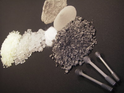
Metal powder injection molding: Top right the metal powders and polymer components left, center: the mixed Granualt. Below: component precursors, and the final Mg-Ca-bone screw to the right. [Photo:HZG/M. Wolff]


Is a paradigm shift imminent in the field of implant materials? Scientists at the Helmholtz Zentrum Geesthacht are engaged in research on biodegradable magnesium biomaterials which can be used as bone replacements in medical applications. They will present their research results from the 1st to 3rd November at the annual congress of the DGBM (German society for Biomaterials) in Hamburg.


When autumn arrives it brings wind and rain, leaves fall from the trees and settle on the ground. If someone slips on them, a bone can easily be broken. When a nail or a plate is required for the fixation of such a bone fracture, it is nowadays usually made of titanium, as this material is stable and well-tolerated by the human body. However, this foreign body must often be removed after the bone has healed, as there is otherwise a danger of inflammation or even bone loss.

According to Prof. Dr. Regine Willumeit, the head of the ‘Structural Research on Macromolecules’ department at the Helmholtz-Zentrum Geesthacht: “The aim of modern implant research is to develop a material which can be used in the body like a real replacement material. A biomaterial which at first supports the bone but then disappears of its own accord after the bone has recovered”.

Magnesium is excellently suited to this purpose. This element is naturally present in the human body and has the advantage that it can biodegrade in a pre-determined manner. It must, thereby, be both light and strong but also well-tolerated by the body. Research scientists at the Helmholtz-Zentrum in Geesthacht are therefore focussing their attention on this particular biomaterial.

The Helmholtz-Zentrum in Geesthacht has shown great expertise for many years in the research and production of prototypes for metallic biodegradable magnesium alloy implants. Material researchers are, for example, engaged in investigations into innovative magnesium-calcium alloys. These reveal material properties similar to those in bone; they are firm and at the same time elastic. Calcium appears to be well suited as an alloy as it would be able to degrade into non-toxic products in the body in the same way as magnesium. The degradation products would even be able to stimulate bone growth.

As Prof. Dr. Regine Willumeit explains: “ We are developing alloys in Geesthacht which have extremely promising properties for use in orthopaedic and traumatological applications. The colleagues at the Magnesium Innovations Center, MagIC, at the HZG, provide us with the starting material, we examine the factors which determine the degradation of the magnesium under physiological conditions”.

Scientists are not only engaged in research into the degradation process of the material itself. Tests are carried out in the Geesthacht laboratories in cell culture on the effects of the degradation on surrounding cells, for example. The scientists involved in this fundamental research into innovative implant materials have comprehensive analysis and test methods at their disposal.

As stable as bone, yet with good biodegradability


Would spare the second operation for removal of screws and plates: implant material of biodegradable magnesium [Photo: Istock 21545233]

The development of production processes is still causing researchers headaches. However, they have also made great progress in this area. The scientist Martin Wolff, from the powder technology department, has, for the first time, succeeded in producing magnesium-calcium bone screws by means of the metal powder injection molding process (MIM). 

As he explains: “The challenge in the case of magnesium lies in the high affinity of this material for oxygen. However, even small amounts of oxygen lead to dramatic changes in the mechanical properties of the component. Calcium, as an alloy partner, captures the oxygen in the production process during the so-called sintering procedure, and the material thus becomes firmer. This non-toxic alloying element has proved successful in achieving better results, at least in experiments. However, numerous further investigations now lie ahead, e.g. in cell culture and in the organism, before this material can be utilized as an implant material.

The Helmholtz researchers from Geesthacht will present their results at the Annual Congress of the Deutsche Gesellschaft für Biomaterialien, DGBM (German Society for Biomaterials), which is to be held at the Chamber of Commerce in Hamburg from 1st to 3rd of November 2012. The main focus this year will be on “Degradable Implants and Biomaterials”. The Congress will be led by Prof. Dr. Regine Willumeit.

Source:  Helmholtz Zentrum Geesthacht


Additional Information:
 
  • Poster Rapid Fire Presentation

New format for the presentation of research results. The scientist’s own research field and results must be clearly presented in only five minutes.
  • Metal powder injection moulding MIM

MIM uses injection moulding technology for the shaping process, which is also widely used in the field of plastics. The starting material is a fine metal powder which is mixed with a so-called binder. This mixture is fused at approx. 100 degrees centigrade. The binder is then chemically removed from the injection moulded part so that only the metal remains. The powder is compacted to the desired firm and dense body by means of a sintering process. 


Friday 26 October 2012

Reclaiming rare earths: Laboratory improving process to recycle rare-earth materials

Engineerblogger
Oct 26, 2012
 
Rare-earth magnet scraps are melted in a furnace with magnesium.
Scientists at the Ames Laboratory are improving the process to reclaim
rare-earth materials.

Recycling keeps paper, plastics, and even jeans out of landfills. Could recycling rare-earth magnets do the same? Perhaps, if the recycling process can be improved.

Scientists at the U.S. Department of Energy’s (DOE) Ames Laboratory are working to more effectively remove the neodymium, a rare earth element, from the mix of other materials in a magnet. Initial results show recycled materials maintain the properties that make rare-earth magnets useful.

The current rare earth recycling research builds on Ames Laboratory’s decades of rare-earth processing experience. In the 1990s, Ames Lab scientists developed a process that uses molten magnesium to remove rare earths from neodymium-iron-boron magnet scrap. Back then, the goal was to produce a mixture of magnesium and neodymium because the neodymium added important strength to the alloy, rather than separate out high-purity rare earths because, at the time, rare earth prices were low.

But rare earth prices increased ten-fold between 2009 and 2011 and supplies are in question. Therefore, the goal of today’s rare-earth recycling research takes the process one step farther.

“Now the goal is to make new magnet alloys from recycled rare earths. And we want those new alloys to be similar to alloys made from unprocessed rare-earth materials,” said Ryan Ott, the Ames Laboratory scientist leading the research. “It appears that the processing technique works well. It effectively removes rare earths from commercial magnets.”

Ott’s research team also includes Ames Laboratory scientist Larry Jones and is funded through a work for others agreement with the Korea Institute of Industrial Technology. The research group is developing and testing the technique in Ames Lab’s Materials Preparation Center, with a suite of materials science tools supported by the DOE Office of Science.

“We start with sintered, uncoated magnets that contain three rare earths: neodymium, praseodymium and dysprosium,” said Ott. “Then we break up the magnets in an automated mortar and pestle until the pieces are 2-4 millimeters long.

Next, the tiny magnet pieces go into a mesh screen box, which is placed in a stainless-steel crucible. Technicians then add chunks of solid magnesium.

A radio frequency furnace heats the material. The magnesium begins to melt, while the magnet chunks remain solid.

“What happens then is that all three rare earths leave the magnetic material by diffusion and enter the molten magnesium,” said Ott. “The iron and boron that made up the original magnet are left behind.”

The molten magnesium and rare-earth mixture is cast into an ingot and cooled. Then they boil off the magnesium, leaving just the rare earth materials behind.

“We’ve found that the properties of the recycled rare earths compare very favorably to ones from unprocessed materials,” said Ott. “We’re continuing to identify the ideal processing conditions.”

The next step is optimizing the extraction process. Then the team plans to demonstrate it on a larger scale.

“We want to help bridge the gap between the fundamental science and using this science in manufacturing,” said Ott. “And Ames Lab can process big enough amounts of material to show that our rare-earth recycling process works on a large scale.”

Source: Ames Laboratory

Electron 'sniper' targets graphene

Engineerblogger
Oct 26, 2012


Credit: Oxford University

Because of its intriguing properties graphene could be the ideal material for building new kinds of electronic devices such as sensors, screens, or even quantum computers.

One of the keys to exploiting graphene's potential is being able to create atomic-scale defects – where carbon atoms in its flat, honeycomb-like structure are rearranged or 'knocked out' – as these influence its electrical, chemical, magnetic, and mechanical properties.

A team led by Oxford University scientists report in Nature Communications a new approach to a new approach to engineering graphene's atomic structure with unprecedented precision.

'Current approaches for producing defects in graphene are either like a 'shotgun' where the entire sample is sprayed with high energy ions or electrons to cause widespread defects, or a chemistry approach where many regions of the graphene are chemically reacted,' said Jamie Warner from Oxford University's Department of Materials, a member of the team.

'Both methods lack any form of control in terms of spatial precision and also the defect type, but to date are the only reported methods known for defect creation.'

The new method replaces the 'shotgun' with something more like a sniper rifle: a minutely-controlled beam of electrons fired from an electron microscope.

'The shotgun approach is restricted to micron scale precision, which is roughly an area of 10,000,000 square nanometres, we demonstrated a precision to within 100 square nanometres, which is about four orders of magnitude better,' explains Alex Robertson of Oxford University's Department of Materials, another member of the team.

Yet it isn’t just about the accuracy of a single 'shot'; the researchers also show that by controlling the length of time graphene is exposed to their focused beam of electrons they can control the size and type of defect created.

'Our study reveals for the first time that only a few types of defects are actually stable in graphene, with several defects being quenched by surface atoms or relaxing back to pristine by bond rotations,' Jamie tells me.

The ability to create just the right kind of stable defects in graphene's crystal structure is going to be vital if its properties are to be harnessed for applications such as mobile phones and flexible displays.

'Defect sites in graphene are much more chemically reactive, so we can use defects as a site for chemical functionalisation of the graphene. So we can attach certain molecules, such as biomolecules, to the graphene to act as a sensor,' Alex tells me.

'Defects in graphene can also give rise to localized electron spin, an attribute that has important future use in quantum nanotechnology and quantum computers.'

At the moment scaling up the team's technique into a manufacturing process to create graphene-based technologies is still a way off. Currently electron microscopes are the only systems that can achieve the necessary exquisite control of an electron beam.

But, Alex says, it is always possible that a scalable electron beam lithography type technique may be developed in the future that could allow for defect patterning in graphene.And it's worth remembering that it wasn't so long ago that the technology needed to etch millions of transistors onto a tiny slice of silicon seemed like an impossible dream.

Source: Oxford University

Additional Information:

Abu Dhabi Scientists Create Desert Rainstorms: Report

Engineerblogger
Oct 26, 2012
Credit: AP

Desert dwellers wishing to transform their arid surroundings into a profitable, crop-sustaining oasis have reportedly gotten one step closer to making that dream a reality, as Abu Dhabi scientists now claim to have created more than 50 artificial rainstorms from clear skies during peak summer months in 2010.

According to Arabian Business, the storms were part of a top secret, Swiss-backed project, commissioned by Sheikh Khalifa bin Zayed Al Nahyan, president of the UAE and leader of Abu Dhabi. Called "Weathertec," the climate project -- said to be worth a staggering $11 million -- utilized ionizers resembling giant lampshades to generate fields of negatively charged particles, which create cloud formation, throughout the country's Al Ain region, the Telegraph is reporting.

"We are currently operating our innovative rainfall enhancement technology, Weathertec, in the region of Al Ain in Abu Dhabid," Helmut Fluhrer, the founder of Metro Systems International, the Swiss company in charge of the project, is quoted as saying. "We started in June 2010 and have achieved a number of rainfalls."

Monitored by the Max Planck Institute for Technology, a leading tank for the study of atmosphere physics, the fake storms are said to have baffled Abu Dhabi residents by also producing hail, wind gales and even lightning.

"There are many applications," Professor Hartmut Grassl, a former institute director, is quoted by the Daily Mail as saying. "One is getting water into a dry area. Maybe this is a most important point for mankind."

Source: Huffington Post

Related Information:

Sunday 9 September 2012

Using magnetism to understand superconductivity

Engineerblogger
Sept 10, 2012

 
© Brookhaven National Laboratory

EPFL research in atomic scale magnetism could play a role in the development of new materials that could permit lossless electricity transmission.

Might it one day be possible to transmit electricity from an offshore wind turbine to land-based users without any loss of current? Materials known as “high temperature” superconductors (even though they must be maintained at -140°C!), which can conduct electricity without any losses, were supposed to make this dream a reality. But over the past twenty-five years, scientists have not been able to make any progress in this area. Research being done in collaboration between Brookhaven National Laboratory (BNL) and EPFL’s Laboratory for Quantum Magnetism (LQM) could change that. Their study of magnetism at extremely small scales could give physicists a tool to use in their search for new superconducting materials.

Studying a superthin layer

There are some ceramics that are excellent insulators at room temperature but that become perfect conductors when submersed in liquid nitrogen. However, this phenomenon, known as “high temperature” superconductivity, is not at all well understood by physicists. They theorize that at these temperatures, the collective quantum magnetic properties of the atoms in the material might come into play. But studying the magnetic properties of these materials at this minuscule scale would require years of effort.

Mark Dean, John Hill and Ivan Bozovic from Brookhaven National Laboratory (BNL), Thorsten Schmitt from Switzerland’s Paul Scherrer Institut (PSI), and Bastien Dalla Piazza and Henrik Ronnow from EPFL have unveiled the phenomena at work at this atomic scale. Using a unique device, the Brookhaven team created a layer just a single atom thick. Then, despite the material’s extreme thinness, the PSI scientists were able to use an ultrasensitive instrument to measure the magnetic dynamics of the atoms. And then EPFL provided the final piece of the puzzle, with mathematical models to analyze the measurements.

A long-awaited research tool


“We now have a kind of flashlight that will show us what direction we should take in our search,” explains Ronnow. Without understanding how these superconducting properties occurred at these temperatures, researchers were probing in the dark, using trial and error, to explore promising new materials. By combining these results with other recent work done by LQM researcher Nikolai Tsyrulin, the EPFL team has provided a new method to help physicists in their search for new superconductors. It’s a long-awaited step forward in the field; the Nobel Prize recognizing the discovery of high temperature superconductivity was awarded more than 25 years ago.

Promises for the future

Electrical resistance in traditional power lines leads to energy losses on the order of 3% in the electricity grid. At the scale of an entire country, this translates into several thousand gigawatts, which, in Switzerland’s case, would be the equivalent of the electricity consumption of a city the size of Geneva. “The energy challenges we face are significant; being able to use superconductivity won’t solve all of them, but it would nonetheless enable huge energy savings,” Ronnow adds.

Source: EPFL

Additional Information: 

Related Article:

Honda Develops New Technology to Weld Together Steel and Aluminum and Achieves World's First Application to the Frame of a Mass-production Vehicle

Engineerblogger
Sept. 9, 2012


Front Subframe


Honda Motor Company announced that it has newly developed a technology for the continuous welding of the dissimilar metals of steel and aluminum and applied it for the first time in the world to the subframe of a mass-production vehicle, a key component of a vehicle body frame. Honda will adopt this technology first to the North American version of the all-new 2013 Accord, which will go on sale in the United States on September 19, 2012, and will expand application sequentially to other models.


Conceptual diagram of FSW of dissimilar metals

Striving to reduce vehicle weight in order to increase fuel economy, Honda focused on Friction Stir Welding (FSW) and developed a new technology for the continuous welding of steel and aluminum. This technology generates a new and stable metallic bonding between steel and aluminum by moving a rotating tool on the top of the aluminum which is lapped over the steel with high pressure. As a result, the welding strength becomes equal to or beyond conventional Metal Inert Gas (MIG) welding*1.

This new technology contributes to an improvement in fuel economy by reducing body weight by 25% compared to a conventional steel subframe. In addition, electricity consumption during the welding process is reduced by approximately 50%. It also enabled a change in the structure of the subframe and the mounting point of suspension, which increased the rigidity of the mounting point by 20% and also contributed to the vehicle’s dynamic performance.

Furthermore, Honda established a new method to apply this technology to mass-production vehicles. Conventionally, FSW required use of large equipment, but Honda developed a FSW continuous welding system applied to a highly versatile industrial robot. This system also can be used for aluminum-to-aluminum welding and thus, the welding system with the same specifications can be used for production of a full-aluminum subframe.

Honda also developed a non-destructive inspection system*2 using a highly-sensitive infrared camera and laser beam, which enables an in-line inspection of the bonding location for every unit.

*1 A welding technique most commonly used for welding of identical materials such as steel-to-steel or aluminum-to-aluminum
*2A system that evaluates quality without actually destructing the parts


Source: Honda

Could ancient Egyptians hold the key to 3D printed ceramics?

Engineerblogger
Sept 3, 2012


Video: Professor Stephen Hoskins shares more about the latest 3D printing methods in ceramics in this insightful interview.
A 7,000 year old technique, known as Egyptian Paste (also known as Faience), could offer a potential process and material for use in the latest 3D printing techniques of ceramics, according to researchers at UWE Bristol.

Professor Stephen Hoskins, Director of UWE's Centre for Fine Print Research and David Huson, Research Fellow, have received funding from the Arts and Humanities Research Council (AHRC to undertake a major investigation into a self-glazing 3D printed ceramic, inspired by ancient Egyptian Faience ceramic techniques. The process they aim to develop would enable ceramic artists, designers and craftspeople to print 3D objects in a ceramic material which can be glazed and vitrified in one firing.

The researchers believe that it possible to create a contemporary 3D printable, once-fired, self-glazing, non-plastic ceramic material that exhibits the characteristics and quality of Egyptian Faience.

Faience was first used in the 5th Millennium BC and was the first glazed ceramic material invented by man. Faience was not made from clay (but instead composed of quartz and alkali fluxes) and is distinct from Italian Faience or Majolica, which is a tin, glazed earthenware. (The earliest Faience is invariably blue or green, exhibiting the full range of shades between them, and the colouring material was usually copper). It is the self-glazing properties of Faience that are of interest for this research project.

Current research in the field of 3D printing concentrates on creating functional materials to form physical models. The materials currently used in the 3D printing process, in which layers are added to build up a 3D form, are commonly: UV polymer resins, hot melted 'abs' plastic and inkjet binder or laser sintered, powder materials. These techniques have previously been known as rapid prototyping (RP). With the advent of better materials and equipment some RP of real materials is now possible. These processes are increasingly being referred to as solid 'free-form fabrication' (SFF) or additive layer manufacture. The UWE research team have focused previously on producing a functional, printable clay body.

This three-year research project will investigate three methods of glazing used by the ancient Egyptians: 'application glazing', similar to modern glazing methods; 'efflorescent glazing' which uses water-soluble salts; and 'cementation glazing', a technique where the object is buried in a glazing powder in a protective casing, then fired.These techniques will be used as a basis for developing contemporary printable alternatives

Professor Hoskins explains, “It is fascinating to think that some of these ancient processes, in fact the very first glazed ceramics every created by humans, could have relevance to the advanced printing technology of today. We hope to create a self-glazing 3D printed ceramic which only requires one firing from conception to completion rather than the usual two. This would be a radical step-forward in the development of 3D printing technologies. As part of the project we will undertake case studies of craft, design and fine art practitioners to contribute to the project, so that our work reflects the knowledge and understanding of artists and reflects the way in which artists work.”

The project includes funding for a three-year full-time PhD bursary to research a further method used by the Egyptians, investigating coloured 'frit', a substance used in glazing and enamels. This student will research this method, investigating the use of coloured frits and oxides to try and create as full a colour range as possible. Once developed, this body will be used to create a ceramic extrusion paste that can be printed with a low-cost 3D printer. A programme of work will be undertaken to determine the best rates of deposition, the inclusion of flocculants and methods of drying through heat whilst printing.

This project offers the theoretical possibility of a printed, single fired, glazed ceramic object - something that is impossible with current technology.

Source: University of the West of England

Manufacturing crack-resistant lightweight components

Enginerblogger
Sept 9, 2012


In this test, the material sample is heated to welding temperature to determine its critical conditions for the formation of cold cracking.  © Chair of Joining and Welding Technology at the Brandenburg University of Technology

Cars, roof structures and bridges should become increasingly lighter, with the same stability, and thus save energy and materials. New high-strength steel is superbly suited for the needed lightweight design, because it can also withstand extremely heavy stresses. Yet these materials also betray a disadvantage: with increasing strength their susceptibility to cold cracking rises when welded. These miniscule fractures might form as the welded joints cool off – typically at temperatures below 200°C. In a worst case scenario, the welding seams would crack. For this reason, many industrial sectors are reluctant to employ these promising high-strength steel.

Scientists at the Fraunhofer Institute for Mechanics of Materials IWM in Freiburg, in conjunction with the Chair of Joining and Welding Technology LFT at Brandenburg University of Technology Cottbus (BTU) developed a new process for making cold cracking more predictable. “We are able to compute the probability of cold cracking as early as the design stage of a component, and immediately run through corrective measures as well,” explains Frank Schweizer of the IWM. Because whether such cold cracking occurs, and how quickly, depends on how high the concentration of hydrogen in the steel is, how the residual stress turns out, and how its microstructure is configured. Predicting the probability of cracking has been difficult until now. Manufacturers used to conduct expensive testing, for example by applying an increasingly higher tensile stress to a sample component, and then analyse what stress level would cause cracking. Not only are these tests time-consuming and cost-intensive, the findings can-
not be applied to subsequent components on a one-to-one basis – because the geometry of the component has a decisive influence on crack formation. Even currently available computer simulations failed to deliver the desired predictive accuracy for real components.

Lowering production costs, shortening development phases

The new approach could markedly reduce such costly methods in the future – and thus lower production costs while shortening development phases. The experts at LFT set up a special test, in order to precisely determine the cracking criterion on samples of highstrength steel. Beside typical influencing factors like hydrogen content, residual stresses and material structures that can be adjusted in at the same time, they also take into account the temperature gradients that emerge in the welding process.

The experts at IWM feed a computer simulation with this criterion in order to analyze the threat of cold cracking in random components and geometries. “This way, we can locate the areas on a welding seam at risk of cold cracking, for each point and at any time in the simulated welding process,” explains Frank Schweizer. The researchers can also get a preliminary look at the effects of any countermeasures, and make the necessary adjustments. To do so, they transfert the results back into the simulation, in order to fine-tune them there.

In the future, with the aid of this process, manufacturers of vehicles and machines could be able to define non-critical welding parameters and limiting conditions for their materials in advance – and thus establish a substantially more efficient and safer production process. This is especially relevant to materials that are difficult to weld, with very narrow processing windows regarding welding parameters or the pre- and post-heating temperatures. Fraunhofer IWM and LFT, in cooperation with Robert Bosch GmbH and ThyssenKrupp Steel Europe AG, are currently testing their new process on laser beam-welded demonstration models made of high-strength steels.

Boaz Almog “levitates” a superconductor

Engineerblogger
Sept 9, 2012


How can a super-thin 3-inch disk levitate something 70,000 times its own weight? In a riveting demonstration, Boaz Almog shows how a phenomenon known as quantum locking allows a superconductor disk to float over a magnetic rail -- completely frictionlessly and with zero energy loss.

Experiment: Prof. Guy Deutscher, Mishael Azoulay, Boaz Almog, of the High Tc Superconductivity Group, School of Physics and Astronomy, Tel Aviv University.

Source: TED

Saturday 8 September 2012

Researchers create tiny, wirelessly powered cardiac device

Engineerblogger
Sept 9, 2012

Ada Poon, assistant professor of electrical engineering, led the research. (Photo: Linda A. Cicero / Stanford News Service)

Stanford electrical engineers overturn existing models to demonstrate the feasibility of a millimeter-sized, wirelessly powered cardiac device. The findings, say the researchers, could dramatically alter the scale of medical devices implanted in the human body.

A team of engineers at Stanford has demonstrated the feasibility of a super-small, implantable cardiac device that gets its power not from batteries but from radio waves transmitted from a small power device on the surface of the body.

The implanted device is contained in a cube just 0.8 millimeter on a side. It could fit on the head of pin.

The findings were published in the journal Applied Physics Letters. In their paper, the researchers demonstrated wireless power transfer to a millimeter-sized device implanted 5 centimeters inside the chest on the surface of the heart – a depth once thought out of reach for wireless power transmission.

The engineers say the research is a major step toward a day when all implants are driven wirelessly. Beyond the heart, they believe such devices might include swallowable endoscopes – so-called "pillcams" that travel the digestive tract – permanent pacemakers and precision brain stimulators – virtually any medical applications where device size and power matter.
A revolution in the body

Implantable medical devices in the human body have revolutionized medicine. Hundreds of thousands if not millions of pacemakers, cochlear implants and drug pumps are today helping patients live relatively normal lives, but these devices are not without engineering challenges.

First, they require power, which means batteries, and batteries are bulky. In a device like a pacemaker, the battery alone accounts for as much as half the volume of the device. Second, batteries have finite lives. New surgery is needed when they wane.

"Wireless power solves both challenges," said Ada Poon, assistant professor of electrical engineering, who headed up the research. She was assisted by Sanghoek Kim and John Ho, both doctoral candidates in her lab.

Last year, Poon made headlines when she demonstrated a wirelessly powered, self-propelled device capable of swimming through the bloodstream. To get there she needed to overturn some long-held assumptions about delivery of wireless power through the human body.

Her latest device works by a combination of inductive and radiative transmission of power. Both are types of electromagnetic transfer in which a transmitter sends radio waves to a coil of wire inside the body. The radio waves produce an electrical current in the coil sufficient to operate a small device.

There is an indirect relationship between the frequency of the transmitted radio waves and the size of the receiving antenna. That is, to deliver a desired level of power, lower frequency waves require bigger coils. Higher frequency waves can work with smaller coils.

"For implantable medical devices, therefore, the goal is a high-frequency transmitter and a small receiver, but there is one big hurdle," Kim said.
Ignoring consensus

Existing mathematical models have held that high-frequency radio waves do not penetrate far enough into human tissue, necessitating the use of low-frequency transmitters and large antennas – too large to be practical for implantable devices.

Ignoring the consensus, Poon proved the models wrong. Human tissues dissipate electric fields quickly, it is true, but radio waves can travel in a different way – as alternating waves of electric and magnetic fields. With the correct equations in hand, she discovered that high-frequency signals travel much deeper than anyone suspected.

"In fact, to achieve greater power efficiency, it is actually advantageous that human tissue is a very poor electrical conductor," said Kim. "If it were a good conductor, it would absorb energy, create heating and prevent sufficient power from reaching the implant."

According to their revised models, the researchers found that the maximum power transfer through human tissue occurs at about 1.7 billion cycles per second, much higher than previously thought.

"In this high-frequency range, we can increase power transfer by about 10 times over earlier devices," said Ho, who honed the mathematical models.

The discovery meant that the team could shrink the receiving antenna by a factor of 10 as well, to a scale that makes wireless implantable devices feasible. At the optimal frequency, a millimeter-radius coil is capable of harvesting more than 50 microwatts of power, well in excess of the needs of a recently demonstrated 8-microwatt pacemaker.
Engineering challenges

With the dimensional challenges solved, the team found itself bound by other engineering constraints. First, electronic medical devices must meet stringent health standards established by IEEE (Institute of Electrical and Electronics Engineers), particularly with regard to tissue heating. Second, the team found that the receiving and transmitting antennas had to be optimally oriented to achieve maximum efficiency. Differences in alignment of just a few degrees could produce troubling drops in power.

"This can't happen medical devices," said Poon. "As the human heart and body are in constant motion, solving this issue was critical to the success of our research." The team responded by designing an innovative slotted transmitting antenna structure. It delivers consistent power efficiency regardless of orientation of the two antennas.

The new design serves additionally to focus the radio waves precisely at the point inside the body where the implanted device rests on the surface of the heart – increasing the electric field where it is needed most, but canceling it elsewhere. This helps reduce overall tissue heating to levels well within the IEEE standards. Poon has applied for a patent on the antenna structure.

This research was made possible by funding from the C2S2 Focus Center, one of six research centers funded under the Focus Center Research Program, a Semiconductor Research Corporation entity. Lisa Chen also contributed to this study.

Source: Stanford University

Researchers Develop New, Less Expensive Nanolithography Technique

Engineerblogger
Sept 9, 2012


This technique uses no electronic components to bring the cantilevers into contact with the substrate surface.

Researchers from North Carolina State University have developed a new nanolithography technique that is less expensive than other approaches and can be used to create technologies with biomedical applications.

“Among other things, this type of lithography can be used to manufacture chips for use in biological sensors that can identify target molecules, such as proteins or genetic material associated with specific medical conditions,” says Dr. Albena Ivanisevic, co-author of a paper describing the research. Ivanisevic is an associate professor of materials science and engineering at NC State and associate professor of the joint biomedical engineering program at NC State and the University of North Carolina at Chapel Hill. Nanolithography is a way of printing patterns at the nanoscale.

The new technique relies on cantilevers, which are 150-micron long silicon strips. The cantilevers can be tipped with spheres made of polymer or with naturally occurring spores. The spheres and spores are coated with ink and dried. The spheres and spores are absorbent and will soak up water when exposed to increased humidity.

As a result, when the cantilevers are exposed to humidity in a chamber, the spheres and spores absorb water – making the tips of the cantilevers heavier and dragging them down into contact with any chosen surface.

Users can manipulate the size of the spheres and spores, which allows them to control the patterns created by the cantilevers. For example, at low humidity, a large sphere will absorb more water than a small sphere, and will therefore be dragged down into contact with the substrate surface. The small sphere won’t be lowered into contact with the surface until it is exposed to higher humidity and absorbs more water.

Further, the differing characteristics of sphere polymers and spores mean that they absorb different amounts of water when exposed to the same humidity – giving users even more control of the nanolithography.

“This technique is less expensive than other device-driven lithography techniques used for microfabrication because the cantilevers do not rely on electronic components to bring the cantilevers into contact with the substrate surface,” Ivanisevic says. “Next steps for this work include using this approach to fabricate lithographic patterns onto tissue for use in tissue regeneration efforts.”

The paper, “Parallel Dip-Pen Nanolithography using Spore- and Colloid-Terminated Cantilevers,” was published online Aug. 17 in the journal Small. Lead author of the paper is Dr. Marcus A. Kramer, who did the work at NC State while completing his Ph.D. at Purdue University.


Source: North Carolina State University

Reference Material Could Aid Nanomaterial Toxicity Research

Engineerblogger
Sept 9, 2012


TEM image shows the nanoscale crystalline structure of titanium dioxide in NIST SRM 1898 (color added for clarity.)  Credit: Impellitteri/EPA
The National Institute of Standards and Technology (NIST) has issued a new nanoscale reference material for use in a wide range of environmental, health and safety studies of industrial nanomaterials. The new NIST reference material is a sample of commercial titanium dioxide powder commonly known as “P25.”

NIST Standard Reference Materials® (SRMs) are typically samples of industrially or clinically important materials that have been carefully analyzed by NIST. They are provided with certified values for certain key properties so that they can be used in experiments as a known reference point.

Nanoscale titanium-dioxide powder may well be the most widely manufactured and used nanomaterial in the world, and not coincidentally, it is also one of the most widely studied. In the form of larger particles, titanium dioxide is a common white pigment. As nanoscale particles, the material is widely used as a photocatalyst, a sterilizing agent and an ultraviolet blocker (in sunscreen lotions, for example).

“Titanium dioxide is not considered highly toxic and, in fact, we don’t certify its toxicity,” observes NIST chemist Vincent Hackley. “But it’s a representative industrial nanopowder that you could include in an environmental or toxicity study. It’s important in such research to include measurements that characterize the nanomaterial you’re studying—properties like morphology, surface area and elemental composition. We’re providing a known benchmark.”

The new titanium-dioxide reference material is a mixed phase, nanocrystalline form of the chemical in a dry powder. To assist in its proper use, NIST also has developed protocols* for properly preparing samples for environmental or toxicological studies.

The new SRM also is particularly well suited for use in calibrating and testing analytical instruments that measure specific surface area of nanomaterials by the widely used Brunauer-Emmet-Teller (BET) gas sorption method.

Additional details and purchasing information on NIST Standard Reference Material 1898, “Titanium Dioxide Nanomaterial” are available at www.nist.gov/srm/index.cfm.

SRMs are among the most widely distributed and used products from NIST. The agency prepares, analyzes and distributes nearly 1,300 different materials that are used throughout the world to check the accuracy of instruments and test procedures used in manufacturing, clinical chemistry, environmental monitoring, electronics, criminal forensics and dozens of other fields.


Source: The National Institute of Standards and Technology (NIST)

Additional Information:

Researchers Set World Record for Highest Surface Area Material

Engineerblogger
Sept 9, 2012


Northwestern University researchers have broken a world record by creating two new synthetic materials with the greatest amount of surface areas reported to date.

Named NU-109 and NU-110, the materials belong to a class of crystalline nanostructure known as metal-organic frameworks (MOFs) that are promising vessels for natural gas storage for vehicles, catalysts, and other sustainable materials chemistry.

The materials’ promise lies in their vast internal surface area. If the internal surface area of one NU-110 crystal the size of a grain of salt could be unfolded, the surface area would cover a desktop. Put another way, the internal surface area of one gram of NU-110 would cover one-and-a-half football fields.

A paper describing the findings, “Metal-organic Framework Materials with Ultrahigh Surface Areas: Is the Sky the Limit?” was published August 20 in the Journal of the American Chemical Society.

The research team, led by Omar Farha, research associate professor of chemistry in the Weinberg College of Arts and Sciences, has synthesized, characterized, and computationally simulated the behavior of the two MOFs that display the highest experimental Brunauer-Emmett-Teller surface areas of any porous material on record, 7,000 m2/g; that is, one kilogram of the material contains an internal surface area that could cover seven square kilometers. (Brunauer-Emmett-Teller, or BET, is an analysis technique for measuring the surface area of a material.)

The extremely high surface area, which is normally not accessible due to solvent molecules that stay trapped within the pores, was achieved using a carbon dioxide activation technique. As opposed to heating, which can remove the solvent but also damage the MOF material, the carbon dioxide-based technique removes the solvent gently and leaves the pores completely intact.

The development could rapidly lead to further advances. MOFs are composed of organic linkers held together by metal atoms, resulting in a molecular cage-like structure. The researchers believe they may be able to more than double the surface area of the materials by using less bulky linker units in the materials’ design.

The research comes from the labs of Joseph T. Hupp, professor of chemistry in Weinberg, and Randall Q. Snurr, professor of chemical and biological engineering at the McCormick School of Engineering.

Other authors include SonBinh Nguyen, professor of chemistry in Weinberg; Ibrahim Eryazici, Nak Cheon Jeong, Brad G. Hauser, Amy A. Sarjeant, and Christopher E. Wilmer, all of Northwestern; and A. Özgür Yazaydın of the University of Surrey in the United Kingdom.

The MOF-designing and -synthesizing technology is being commercialized by NuMat Technologies, a Northwestern startup that has won more than $1 million in business plan competitions since incorporating in February.

Source:  Northwestern University

Friday 3 August 2012

Transparent solar cells for windows that generate electricity

Engineerblogger
Aug 3, 2012


Visibly transparent photovoltaic devices can open photovoltaic applications in many areas, such as building-integrated photovoltaics or integrated photovoltaic chargers for portable electronics. We demonstrate high-performance, visibly transparent polymer solar cells fabricated via solution processing. The photoactive layer of these visibly transparent polymer solar cells harvests solar energy from the near-infrared region while being less sensitive to visible photons. The top transparent electrode employs a highly transparent silver nanowire–metal oxide composite conducting film, which is coated through mild solution processes. With this combination, we have achieved 4% power-conversion efficiency for solution-processed and visibly transparent polymer solar cells. The optimized devices have a maximum transparency of 66% at 550 nm.


Scientists are reporting development of a new transparent solar cell, an advance toward giving windows in homes and other buildings the ability to generate electricity while still allowing people to see outside. Their report appears in the journal ACS Nano.

Yang Yang, Rui Zhu, Paul S. Weiss and colleagues explain that there has been intense world-wide interest in so-called polymer solar cells (PSCs), which are made from plastic-like materials. PSCs are lightweight and flexible and can be produced in high volume at low cost. That interest extends to producing transparent PSCs. However, previous versions of transparent PSCs have had many disadvantages, which the team set out to correct.

They describe a new kind of PSC that produces energy by absorbing mainly infrared light, not visible light, making the cells 66 percent transparent to the human eye. They made the device from a photoactive plastic that converts infrared light into an electrical current. Another breakthrough is the transparent conductor made of a mixture of silver nanowire and titanium dioxide nanoparticles, which was able to replace the opaque metal electrode used in the past. This composite electrode also allowed the solar cell to be fabricated economically by solution processing. The authors suggest the panels could be used in smart windows or portable electronics.

The authors acknowledge funding from the Engineering School of UCLA, the Office of Naval Research and the Kavli Foundation.

Source: American Chemical Society 

Additional Information:

The first robot that mimics the water striders’ jumping abilities

Engineerblogger
Aug 3, 2012


Credit: American Chemical Society

The first bio-inspired microrobot capable of not just walking on water like the water strider – but continuously jumping up and down like a real water strider – now is a reality. Scientists reported development of the agile microrobot, which could use its jumping ability to avoid obstacles on reconnaissance or other missions, in ACS Applied Materials & Interfaces.

Qinmin Pan and colleagues explain that scientists have reported a number of advances toward tiny robots that can walk on water. Such robots could skim across lakes and other bodies of water to monitor water quality or act as tiny spies. However, even the most advanced designs – including one from Pan’s team last year – can only walk on water. Pan notes that real water striders actually leap. Making a jumping robot is difficult because the downward force needed to propel it into the air usually pushes the legs through the water’s surface. Pan’s group looked for novel mechanisms and materials to build a true water-striding robot.

Using porous, super water-repellant nickel foam to fabricate the three supporting and two jumping legs, the group made a robot that could leap more than 5.5 inches, despite weighing as much as 1,100 water striders. In experiments, the robot could jump nearly 14 inches forward – more than twice its own length – leaving the water at about 3.6 miles per hour. The authors report that the ability to leap will make the bio-inspired microrobot more agile and better able to avoid obstacles it encounters on the water’s surface.

The authors acknowledge funding from the State Key Laboratory of Robotics and System of Harbin Institute of Technology and the National Natural Science Foundation of China.


Source:  American Chemical Society

Additional Information:

Printing 3D Blood Vessel Networks out of Sugar

Engineerblogger
Aug 3, 2012


3D Printing Blood Vessel Networks


Scientists can already grow thin layers of cells, so one proposed solution to the vasculature problem is to “print” the cells layer by layer, leaving openings for blood vessels as necessary. But this method leaves seams, and when blood is pumped through the vessels, it pushes those seams apart.

Bioengineers from the University of Pennsylvania have turned the problem inside out by using a 3D printer called a RepRap to make templates of blood vessel networks out of sugar. Once the networks are encased in a block of cells, the sugar can be dissolved, leaving a functional vascular network behind.

“I got the first hint of this solution when I visited a Body Worlds exhibit, where you can see plastic casts of free-standing, whole organ vasculature,” says Bioengineering postdoc Jordan Miller.

Miller, along with Christopher Chen, the Skirkanich Professor of Innovation in the Department of Bioengineering, other members of Chen’s lab, and colleagues from MIT, set out to show that this method of developing sugar vascular networks helps keep interior cells alive and functioning.

After the researchers design the network architecture on a computer, they feed the design to the RepRap. The printer begins building the walls of a stabilizing mold. Then it then draws filaments across the mold, pulling the sugar at different speeds to achieve the desired thickness of what will become the blood vessels.

After the sugar has hardened, the researchers add liver cells suspended in a gel to the mold. The gel surrounds the filaments, encasing the blood vessel template. After the gel sets it can be removed from the mold with the template still inside. The block of gel is then washed in water, dissolving the remaining sugar inside. The liquid sugar flows out of the vessels it has created without harming the growing cells.

“This new technology, from the cell’s perspective, makes tissue formation a gentle and quick journey,” says Chen.

The researchers have successfully pumped nutrient-rich media, and even blood, through these gels blocks’ vascular systems. They also have experimentally shown that more of the liver cells survive and produce more metabolites in gels that have these networks.

The RepRap makes testing new vascular architectures quick and inexpensive, and the sugar is stable enough to ship the finished networks to labs that don’t have 3D printers of their own. The researchers hope to eventually use this method to make implantable organs for animal studies.

Source: 
University of Pennsylvania

Thursday 19 July 2012

Engineers develop an ‘intelligent co-pilot’ for cars

Engineerblogger
July 19, 2012


Barrels and cones dot an open field in Saline, Mich., forming an obstacle course for a modified vehicle. A driver remotely steers the vehicle through the course from a nearby location as a researcher looks on. Occasionally, the researcher instructs the driver to keep the wheel straight — a trajectory that appears to put the vehicle on a collision course with a barrel. Despite the driver’s actions, the vehicle steers itself around the obstacle, transitioning control back to the driver once the danger has passed.

The key to the maneuver is a new semiautonomous safety system developed by Sterling Anderson, a PhD student in MIT’s Department of Mechanical Engineering, and Karl Iagnemma, a principal research scientist in MIT’s Robotic Mobility Group.

The system uses an onboard camera and laser rangefinder to identify hazards in a vehicle’s environment. The team devised an algorithm to analyze the data and identify safe zones — avoiding, for example, barrels in a field, or other cars on a roadway. The system allows a driver to control the vehicle, only taking the wheel when the driver is about to exit a safe zone.

Anderson, who has been testing the system in Michigan since last September, describes it as an “intelligent co-pilot” that monitors a driver’s performance and makes behind-the-scenes adjustments to keep the vehicle from colliding with obstacles, or within a safe region of the environment, such as a lane or open area.

“The real innovation is enabling the car to share [control] with you,” Anderson says. “If you want to drive, it’ll just … make sure you don’t hit anything.”

The group presented details of the safety system recently at the Intelligent Vehicles Symposium in Spain.

Off the beaten path

Robotics research has focused in recent years on developing systems — from cars to medical equipment to industrial machinery — that can be controlled by either robots or humans. For the most part, such systems operate along preprogrammed paths.

As an example, Anderson points to the technology behind self-parking cars. To parallel park, a driver engages the technology by flipping a switch and taking his hands off the wheel. The car then parks itself, following a preplanned path based on the distance between neighboring cars.

While a planned path may work well in a parking situation, Anderson says when it comes to driving, one or even multiple paths is far too limiting.

“The problem is, humans don’t think that way,” Anderson says. “When you and I drive, [we don’t] choose just one path and obsessively follow it. Typically you and I see a lane or a parking lot, and we say, ‘Here is the field of safe travel, here’s the entire region of the roadway I can use, and I’m not going to worry about remaining on a specific line, as long as I’m safely on the roadway and I avoid collisions.’”

Anderson and Iagnemma integrated this human perspective into their robotic system. The team came up with an approach to identify safe zones, or “homotopies,” rather than specific paths of travel. Instead of mapping out individual paths along a roadway, the researchers divided a vehicle’s environment into triangles, with certain triangle edges representing an obstacle or a lane’s boundary.

The researchers devised an algorithm that “constrains” obstacle-abutting edges, allowing a driver to navigate across any triangle edge except those that are constrained. If a driver is in danger of crossing a constrained edge — for instance, if he’s fallen asleep at the wheel and is about to run into a barrier or obstacle — the system takes over, steering the car back into the safe zone.

Building trust

So far, the team has run more than 1,200 trials of the system, with few collisions; most of these occurred when glitches in the vehicle’s camera failed to identify an obstacle. For the most part, the system has successfully helped drivers avoid collisions.

Benjamin Saltsman, manager of intelligent truck vehicle technology and innovation at Eaton Corp., says the system has several advantages over fully autonomous variants such as the self-driving cars developed by Google and Ford. Such systems, he says, are loaded with expensive sensors, and require vast amounts of computation to plan out safe routes.

"The implications of [Anderson's] system is it makes it lighter in terms of sensors and computational requirements than what a fully autonomous vehicle would require," says Saltsman, who was not involved in the research. "This simplification makes it a lot less costly, and closer in terms of potential implementation."

In experiments, Anderson has also observed an interesting human response: Those who trust the system tend to perform better than those who don’t. For instance, when asked to hold the wheel straight, even in the face of a possible collision, drivers who trusted the system drove through the course more quickly and confidently than those who were wary of the system.

And what would the system feel like for someone who is unaware that it’s activated? “You would likely just think you’re a talented driver,” Anderson says. “You’d say, ‘Hey, I pulled this off,’ and you wouldn’t know that the car is changing things behind the scenes to make sure the vehicle remains safe, even if your inputs are not.”

He acknowledges that this isn’t necessarily a good thing, particularly for people just learning to drive; beginners may end up thinking they are better drivers than they actually are. Without negative feedback, these drivers can actually become less skilled and more dependent on assistance over time. On the other hand, Anderson says expert drivers may feel hemmed in by the safety system. He and Iagnemma are now exploring ways to tailor the system to various levels of driving experience.

The team is also hoping to pare down the system to identify obstacles using a single cellphone. “You could stick your cellphone on the dashboard, and it would use the camera, accelerometers and gyro to provide the feedback needed by the system,” Anderson says. “I think we’ll find better ways of doing it that will be simpler, cheaper and allow more users access to the technology.”

This research was supported by the United States Army Research Office and the Defense Advanced Research Projects Agency. The experimental platform was developed in collaboration with Quantum Signal LLC with assistance from James Walker, Steven Peters and Sisir Karumanchi.

Source: MIT News

Autonomous robot scans ship hulls for mines

MIT News
July 17, 2012


Algorithms developed by MIT researchers enable an autonomous underwater vehicle (AUV) to swim around and reconstruct a ship's propeller. 
Image: Franz Hover, Brendan Englo

For years, the U.S. Navy has employed human divers, equipped with sonar cameras, to search for underwater mines attached to ship hulls. The Navy has also trained dolphins and sea lions to search for bombs on and around vessels. While animals can cover a large area in a short amount of time, they are costly to train and care for, and don’t always perform as expected.

In the last few years, Navy scientists, along with research institutions around the world, have been engineering resilient robots for minesweeping and other risky underwater missions. The ultimate goal is to design completely autonomous robots that can navigate and map cloudy underwater environments — without any prior knowledge of those environments — and detect mines as small as an iPod.

Now Franz Hover, the Finmeccanica Career Development Associate Professor in the Department of Mechanical Engineering, and graduate student Brendan Englot have designed algorithms that vastly improve such robots’ navigation and feature-detecting capabilities. Using the group’s algorithms, the robot is able to swim around a ship’s hull and view complex structures such as propellers and shafts. The goal is to achieve a resolution fine enough to detect a 10-centimeter mine attached to the side of a ship.

“A mine this small may not sink the vessel or cause loss of life, but if it bends the shaft, or damages the bearing, you still have a big problem,” Hover says. “The ability to ensure that the bottom of the boat doesn’t have a mine attached to it is really critical to vessel security today.”

Hover and his colleagues have detailed their approach in a paper to appear in theInternational Journal of Robotics Research.

Why platinum is the wrong material for fuel cell?

Engineerblogger
July 19, 2012


Professor Alfred Anderson

Fuel cells are inefficient because the catalyst most commonly used to convert chemical energy to electricity is made of the wrong material, a researcher at Case Western Reserve University argues. Rather than continue the futile effort to tweak that material—platinum—to make it work better, Chemistry Professor Alfred Anderson urges his colleagues to start anew.

“Using platinum is like putting a resistor in the system,” he said. Anderson freely acknowledges he doesn’t know what the right material is, but he’s confident researchers’ energy would be better spent seeking it out than persisting with platinum.

“If we can find a catalyst that will do this [more efficiently],” he said, “it would reach closer to the limiting potential and get more energy out of the fuel cell.”

Anderson’s analysis and a guide for a better catalyst have been published in a recent issue of Physical Chemistry Chemical Physics and in Electrocatalysis online.

Even in the best of circumstances, Anderson explained, the chemical reaction that produces energy in a fuel cell—like those being tested by some car companies—ends up wasting a quarter of the energy that could be transformed into electricity. This point is well recognized in the scientific community, but, to date, efforts to address the problem have proved fruitless.

Anderson blames the failure on a fundamental misconception as to the reason for the energy waste. The most widely accepted theory says impurities are binding to the platinum surface of the cathode and blocking the desired reaction.

“The decades-old surface-poisoning explanation is lame because there is more to the story,” Anderson said.

To understand the loss of energy, Anderson used data derived from oxygen-reduction experiments to calculate the optimal bonding strengths between platinum and intermediate molecules formed during the oxygen-reduction reaction. The reaction takes place at the platinum-coated cathode.

He found the intermediate molecules bond too tightly or too loosely to the cathode surface, slowing the reaction and causing a drop in voltage. The result is the fuel cell produces about .93 volts instead of the potential maximum of 1.23 volts.

To eliminate the loss, calculations show, the catalyst should have bonding strengths tailored so that all reactions taking place during oxygen reduction occur at or as near to 1.23 volts as possible.

Anderson said the use of volcano plots, which are a statistical tool for comparing catalysts, has actually misguided the search for the best one. “They allow you to grade a series of similar catalysts, but they don’t point to better catalysts.”

He said a catalyst made of copper laccase, a material found in trees and fungi, has the desired bonding strength but lacks stability. Finding a catalyst that has both is the challenge.

Anderson is working with other researchers exploring alternative catalysts as well as an alternative reaction pathway in an effort to increase efficiency.


Source: Case Western Reserve University

Researchers Create Highly Conductive and Elastic Conductors Using Silver Nanowires

Engineerblogger
July 19, 2012


The silver nanowires can be printed to fabricate patterned stretchable conductors.


Researchers from North Carolina State University have developed highly conductive and elastic conductors made from silver nanoscale wires (nanowires). These elastic conductors can be used to develop stretchable electronic devices.

Stretchable circuitry would be able to do many things that its rigid counterpart cannot. For example, an electronic “skin” could help robots pick up delicate objects without breaking them, and stretchable displays and antennas could make cell phones and other electronic devices stretch and compress without affecting their performance. However, the first step toward making such applications possible is to produce conductors that are elastic and able to effectively and reliably transmit electric signals regardless of whether they are deformed.

Dr. Yong Zhu, an assistant professor of mechanical and aerospace engineering at NC State, and Feng Xu, a Ph.D. student in Zhu’s lab have developed such elastic conductors using silver nanowires.

Silver has very high electric conductivity, meaning that it can transfer electricity efficiently. And the new technique developed at NC State embeds highly conductive silver nanowires in a polymer that can withstand significant stretching without adversely affecting the material’s conductivity. This makes it attractive as a component for use in stretchable electronic devices.

“This development is very exciting because it could be immediately applied to a broad range of applications,” Zhu said. “In addition, our work focuses on high and stable conductivity under a large degree of deformation, complementary to most other work using silver nanowires that are more concerned with flexibility and transparency.”

“The fabrication approach is very simple,” says Xu. Silver nanowires are placed on a silicon plate. A liquid polymer is poured over the silicon substrate. The polymer is then exposed to high heat, which turns the polymer from a liquid into an elastic solid. Because the polymer flows around the silver nanowires when it is in liquid form, the nanowires are trapped in the polymer when it becomes solid. The polymer can then be peeled off the silicon plate.

“Also silver nanowires can be printed to fabricate patterned stretchable conductors,” Xu says. The fact that it is easy to make patterns using the silver nanowire conductors should facilitate the technique’s use in electronics manufacturing.

When the nanowire-embedded polymer is stretched and relaxed, the surface of the polymer containing nanowires buckles. The end result is that the composite is flat on the side that contains no nanowires, but wavy on the side that contains silver nanowires.

After the nanowire-embedded surface has buckled, the material can be stretched up to 50 percent of its elongation, or tensile strain, without affecting the conductivity of the silver nanowires. This is because the buckled shape of the material allows the nanowires to stay in a fixed position relative to each other, even as the polymer is being stretched.

“In addition to having high conductivity and a large stable strain range, the new stretchable conductors show excellent robustness under repeated mechanical loading,” Zhu says. Other reported stretchable conductive materials are typically deposited on top of substrates and could delaminate under repeated mechanical stretching or surface rubbing.

The paper, “Highly Conductive and Stretchable Silver Nanowire Conductors,” was published in Advanced Materials. The research was supported by the National Science Foundation.


Source:  North Carolina State University


Researchers develop “nanorobot” that can be programmed to target different diseases


Engineerblogger

July 19, 2012


University of Florida researchers have moved a step closer to treating diseases on a cellular level by creating a tiny particle that can be programmed to shut down the genetic production line that cranks out disease-related proteins.

In laboratory tests, these newly created “nanorobots” all but eradicated hepatitis C virus infection. The programmable nature of the particle makes it potentially useful against diseases such as cancer and other viral infections.

The research effort, led by Y. Charles Cao, a UF associate professor of chemistry, and Dr. Chen Liu, a professor of pathology and endowed chair in gastrointestinal and liver research in the UF College of Medicine, is described online this week in the Proceedings of the National Academy of Sciences.

“This is a novel technology that may have broad application because it can target essentially any gene we want,” Liu said. “This opens the door to new fields so we can test many other things. We’re excited about it.”

During the past five decades, nanoparticles — particles so small that tens of thousands of them can fit on the head of a pin — have emerged as a viable foundation for new ways to diagnose, monitor and treat disease. Nanoparticle-based technologies are already in use in medical settings, such as in genetic testing and for pinpointing genetic markers of disease. And several related therapies are at varying stages of clinical trial.

The Holy Grail of nanotherapy is an agent so exquisitely selective that it enters only diseased cells, targets only the specified disease process within those cells and leaves healthy cells unharmed.

To demonstrate how this can work, Cao and colleagues, with funding from the National Institutes of Health, the Office of Naval Research and the UF Research Opportunity Seed Fund, created and tested a particle that targets hepatitis C virus in the liver and prevents the virus from making copies of itself.

Hepatitis C infection causes liver inflammation, which can eventually lead to scarring and cirrhosis. The disease is transmitted via contact with infected blood, most commonly through injection drug use, needlestick injuries in medical settings, and birth to an infected mother. More than 3 million people in the United States are infected and about 17,000 new cases are diagnosed each year, according to the Centers for Disease Control and Prevention. Patients can go many years without symptoms, which can include nausea, fatigue and abdominal discomfort.

Current hepatitis C treatments involve the use of drugs that attack the replication machinery of the virus. But the therapies are only partially effective, on average helping less than 50 percent of patients, according to studies
published in The New England Journal of Medicine and other journals. Side effects vary widely from one medication to another, and can include flu-like symptoms, anemia and anxiety.

Cao and colleagues, including graduate student Soon Hye Yang and postdoctoral associates Zhongliang Wang, Hongyan Liu and Tie Wang, wanted to improve on the concept of interfering with the viral genetic material in a way that boosted therapy effectiveness and reduced side effects.

The particle they created can be tailored to match the genetic material of the desired target of attack, and to sneak into cells unnoticed by the body’s innate defense mechanisms.

Recognition of genetic material from potentially harmful sources is the basis of important treatments for a number of diseases, including cancer, that are linked to the production of detrimental proteins. It also has potential for use in detecting and destroying viruses used as bioweapons.

The new virus-destroyer, called a nanozyme, has a backbone of tiny gold particles and a surface with two main biological components. The first biological portion is a type of protein called an enzyme that can destroy the genetic recipe-carrier, called mRNA, for making the disease-related protein in question. The other component is a large molecule called a DNA oligonucleotide that recognizes the genetic material of the target to be destroyed and instructs its neighbor, the enzyme, to carry out the deed. By itself, the enzyme does not selectively attack hepatitis C, but the combo does the trick.

“They completely change their properties,” Cao said.

In laboratory tests, the treatment led to almost a 100 percent decrease in hepatitis C virus levels. In addition, it did not trigger the body’s defense mechanism, and that reduced the chance of side effects. Still, additional testing is needed to determine the safety of the approach.

Future therapies could potentially be in pill form.

“We can effectively stop hepatitis C infection if this technology can be further developed for clinical use,” said Liu, who is a member of The UF Shands Cancer Center.

The UF nanoparticle design takes inspiration from the Nobel prize-winning discovery of a process in the body in which one part of a two-component complex destroys the genetic instructions for manufacturing protein, and the other part serves to hold off the body’s immune system attacks. This complex controls many naturally occurring processes in the body, so drugs that imitate it have the potential to hijack the production of proteins needed for normal function. The UF-developed therapy tricks the body into accepting it as part of the normal processes, but does not interfere with those processes.

“They’ve developed a nanoparticle that mimics a complex biological machine — that’s quite a powerful thing,” said nanoparticle expert Dr. C. Shad Thaxton, an assistant professor of urology at the Feinberg School of Medicine at Northwestern University and co-founder of the biotechnology company AuraSense LLC, who was not involved in the UF study. “The promise of nanotechnology is extraordinary. It will have a real and significant impact on how we practice medicine.”

Source: University of Florida

The Artificial Finger: New ultracapacitor delivers a jolt of energy at a constant voltage

Engineerblogger
June 19, 2012


To touch something is to understand it – emotionally and cognitive. It´s one of our important six senses, which we use and need in our daily lives. But accidents or illnesses can disrupt us from our sense of touch

To touch something is to understand it – emotionally and cognitive. It´s one of our important six senses, which we use and need in our daily lives. But accidents or illnesses can disrupt us from our sense of touch.

Now European researchers of the projects NanoBioTact and NanoBioTouch delve deep into the mysteries of touch and have developed the first sensitive artificial finger.
The main scientific aims of the projects are to radically improve understanding of the human mechano-transduction system and tissue engineered nanobiosensors. Therefore an international and multi disciplinary team of 13 scientific institutes, universities and companies put their knowledge together. “There are many potential applications of biometric tactile sensoring, for example in prosthetic limbs where you´ve got neuro-coupling which allows the limb to sense objects and also to feed back to the brain, to control the limb. Another area would be in robotics where you might want the capability to have sense the grip of objects, or intelligent haptic exploration of surfaces for example”, says Prof. Michael Adams, the coordinator of NanoBioTact.

The scientists have already developed a prototype of the first sensitive artificial finger. It works with an array of pressure sensors that mimic the spatial resolution, sensitivity and dynamics of human neural tactile sensors and can be directly connected to the central nervous system. Combined with an artificial skin that mimics a human fingerprint, the device´s sensitivity to vibrations is improved. Depending on the quality of a textured surface, the biomimetic finger vibrates in different ways, when it slides across the surface. Thereby it produces different signals and once it will get used by patients, they could recognise if the surface is smooth or scratchy. “The sensors are working very much like the sensors are doing on your own finger”, says physicist Dr. Michael Ward from the School of Mechanical Engineering at the University of Birmingham.

Putting the biomimetic finger on artificial limbs would take prostheses to the next level. “Compared to the hand prostheses which are currently on the market, an integrated sense of touch would be a major improvement. It would be a truly modern and biometric device which would give the patient the feeling as if it belonged to his own body”, says Dr. Lucia Beccai from the Centre for Micro-Robotics at the Italian Institute for Technology. But till the artificial finger will be available on large scale a lot of tests will have to be done. Nevertheless with the combination of computer and cognitive sciences, nano- and biotechnology the projects NanoBioTact and NanoBioTouch have already brought us a big step closer to artificial limbs with sensitive fingers!

Source: Youris